1730–Series Installation
3–3
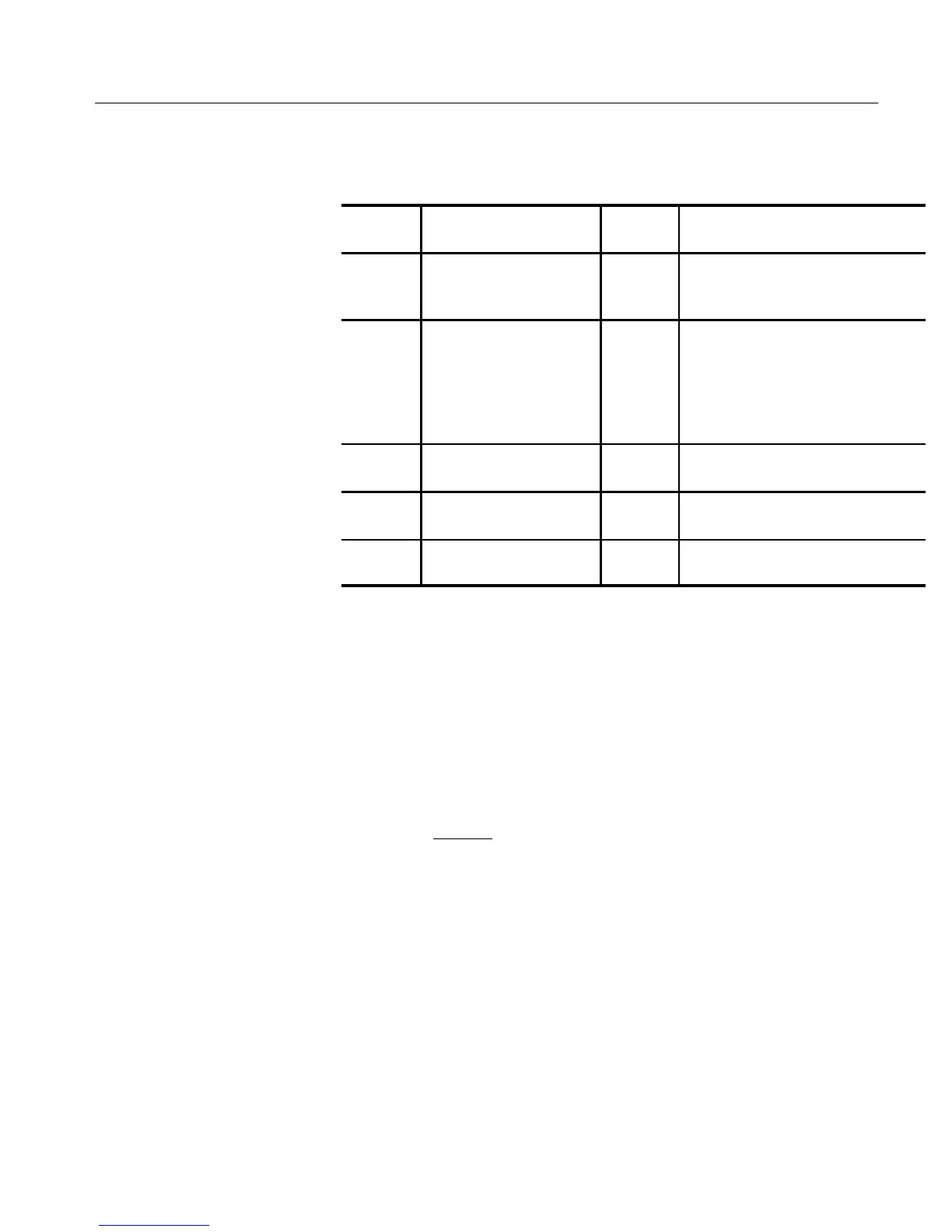
Table 3–1: Internal Jumper Selections
Jumper
Number
PurposePositionName
3
3
3-."+ +,!" # .*,1 +,"3
-".
3-."+ +,!"
2
# .*,1 -".
3
3
3
2 '&)" ,." # .*,1 -". #*,
2 '&)" ,." # .*,1 -". #*,
/(+", &) 3 +*-&.&*) *, ,"3
(*0"!
2 2 3
3
*, 2
&)" &"'! # .*,1 +,"-".
"(*." 1) *',&.1 3
3
*-&.&0" # .*,1 +,"-".
"$.&0"
&$%. )'" 3
3
&$%.- )'"! # .*,1 +,"-".
&$%.- &-'"!
1.
1731 PAL-M requires A3J504 be in the 2-3 position.
2.
Having A3J504 in the 2-3 position inhibits the 1735 standard switching.
REMOTE Connector
The rear-panel REMOTE connector is a 15-pin, D-type connector. It is the
Remote Control Interface, the input for RGB signals and Remote Sync.
Remote functions, which provide switching and recalling of stored front-panel
setups at a remote location, are enabled by ground closures (TTL lows).
Functions with “overbars” indicate an active low state. In addition to the four
front-panel RECALL SETUPs that can be called up remotely, there are four
additional factory-programmed Presets that can only be called up through the
REMOTE connector. Pin assignments for the REMOTE connector are shown in
Figure 3-2 and discussed in Table 3–2.
 Loading...


