1730–Series Maintenance
6–5
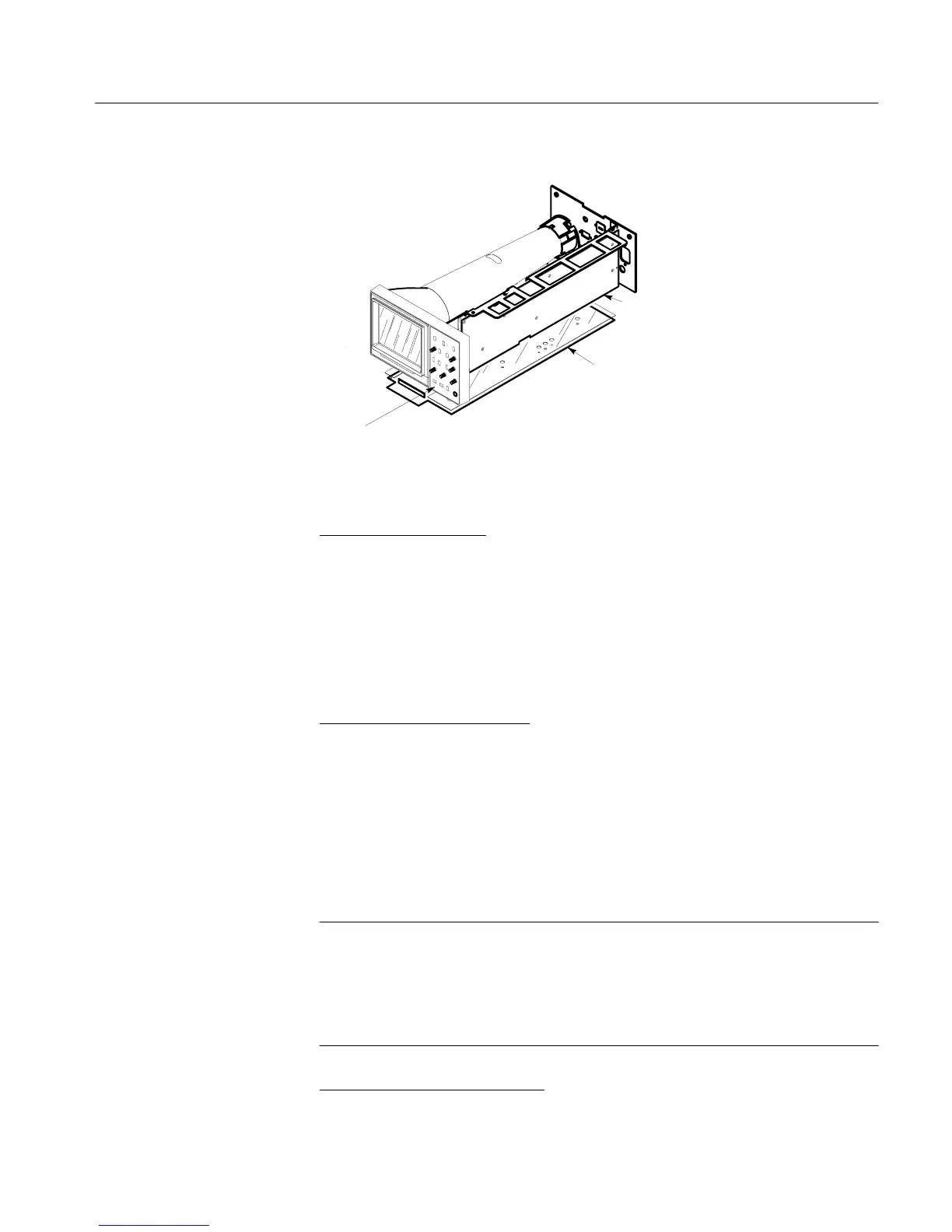
A2 Front Panel Board
A3 Main Board
A1 Power
Supply
Board
Figure 6-1: Circuit board assembly locations.
Adjustment Locations.
Section 5 has illustrations that have the adjustments
and test points called out as calibration and troubleshooting aids.
There are two separate parts lists in this manual. The Replaceable Electrical
Parts list (Section 8) precedes the schematic diagrams and circuit board
illustrations. The Replaceable Mechanical Parts list (Section 10), accompanied
by exploded view drawings, follows the schematic diagrams and circuit board
illustrations.
Replaceable Electrical Parts.
This list is arranged by assembly as designated
in ANSI Standard Y32.16–1975. The list begins with the part numbers for the
major assemblies (etched circuit boards). Each circuit board is identified by an
A# (Assembly Number).
The circuit numbers of the individual components in the parts list are made up
by combining the assembly number with the individual circuit number.
EXAMPLE: R117 on Assembly (circuit board) A3 would be listed in the
Replaceable Electrical Parts list as A3R117.
NOTE. Check Parts Lists:
Replaceable Mechanical Parts. This list is arranged so that it corresponds to
the exploded view drawing for major instrument components. The list and
Parts Lists

 Loading...


