1730–Series Operating Instructions
2–26 REV MAY 1993
120
100
80
60
40
20
–20
–40
1.2
1.0
1.1
0.9
0.8
0.7
0.6
0.5
0.4
0.2
0.1
0
PAL
NTSC
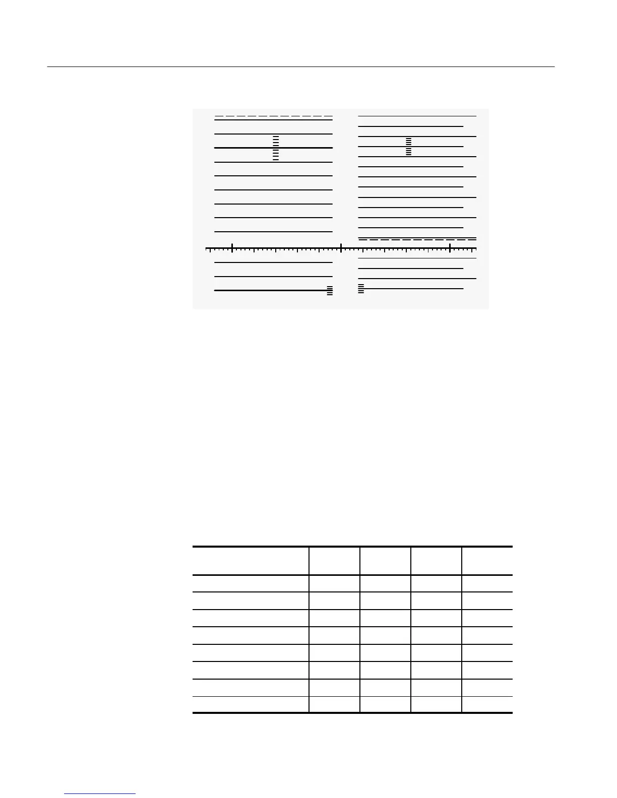
Figure 2-18: Dual standard graticule.
Preset Front-Panel Measurements
The 1730–Series has four front–panel setups stored in internal memory. A TTL
low (or ground closure) on one of the PRESET enables (pins 12 through 15 of
the REMOTE connector) selects one of these pre–programmed, front–panel
setups. Table 2–1 shows the preset front panels that are stored in memory.
When the 1730–Series is used as a direct replacement for the TEKTRONIX
528A Waveform Monitor (which used dc voltage levels as enables), it will be
necessary to use a conversion circuit to change these positive voltage levels to
apparent ground closures. See Figure 3-3 for a simple conversion circuit.
Table 2–1: Preset Front Panels
Front–Panel Control
Preset 1
(pin 13)
Preset 2
(pin 14)
Preset 3
(pin 15)
Preset 4
(pin 12)
INPUT Channel A A A A
INPUT Reference EXT INT INT INT
INPUT Filter FLAT FLAT FLAT FLAT
VERTICAL Gain (VAR) off off off off
VERTICAL Gain (X5) off off off off
VERTICAL DC Restorer OFF OFF SLOW SLOW
HORIZONTAL Field FLD 1 ALL ALL FLD 1
HORIZONTAL Sweep 2 FLD 2 LINE 1 LINE 2 LINE

 Loading...


