4–1
Section 4
Theory of Operation
The material in this section is subdivided into a general description (which is
supported by the main block diagram and simplified block diagrams) and
detailed circuit descriptions that use the schematic diagrams as illustrations. A
thorough understanding of the instrument starts with knowing how the major
circuit blocks fit together, which is then followed by an understanding of the
individual circuit’s functions. These discussions of the 1730-Series Waveform
Monitor begin with a brief, fundamental overview, then proceed on to the block
diagram, and then go into individual circuit descriptions.
VERTICAL
INPUTS
CH A
CH B
EXT REF
FRONT
PANEL
CONTROLS
MICROCONTROLLER
AUXILIARY
INTERFACE
HORIZONTAL
REMOTE
INTERFACE
SYNC
RXD
TXD
LS STROBE
PRESETS
RECAL
REMOTE SYNC
RGB ENABLE
RGB INPUT
CRT
SWITCHING
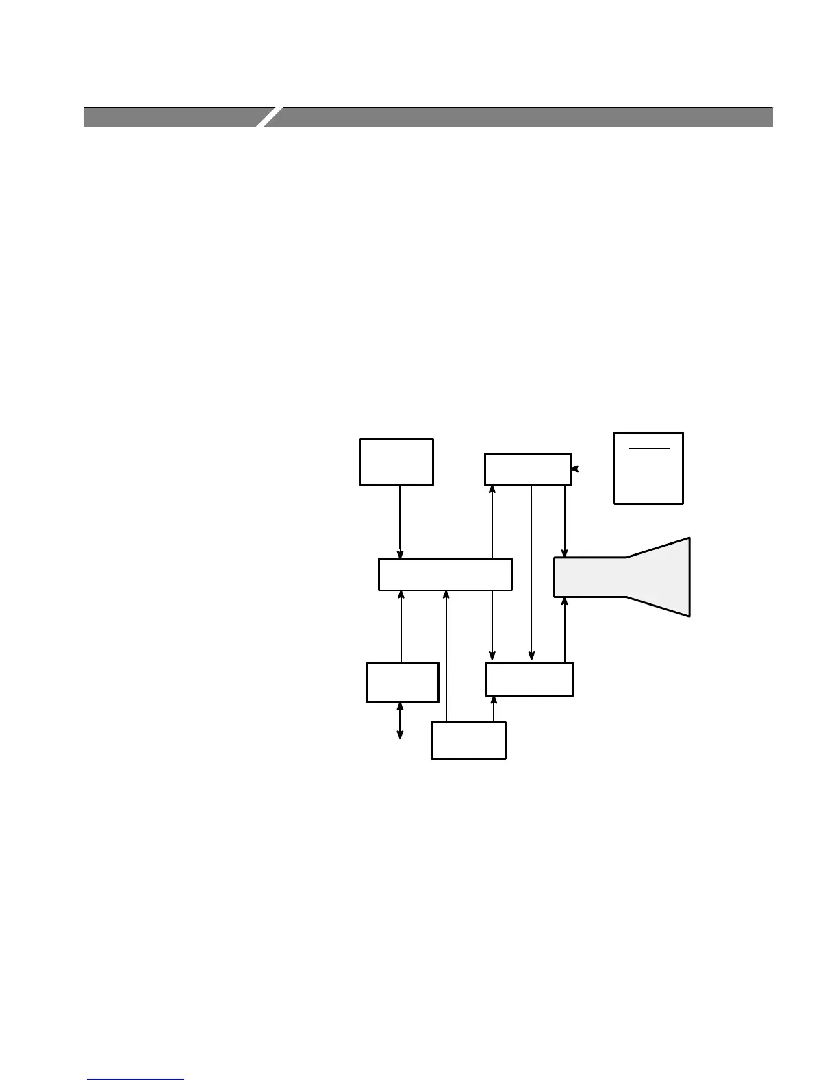
Figure 4-1: Simplified representation of the 1730-Series Waveform Monitor.
Overview
The 1730-Series is a specialized oscilloscope, designed to monitor and measure
television baseband signals. See Figure 4-1. Signals input through either of the
rear-panel 75W bridging loop-through inputs are synchronously displayed on a
CRT. In addition, an alpha-numeric line and field readout is provided on the
CRT for use with the LINE SELECT mode of operation.
 Loading...


