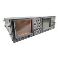
1730–Series Operating Instructions
2–11
NOTE. Front–panel screwdriver adjustments:
Do not set any of the front–panel screwdriver controls until after the instrument
warms up (20 minutes minimum).
3. Initial Front–Panel Setup
1730–Series Waveform Monitor
FILTER FLAT
REF INT
INPUT A
GAIN OFF (no indicators on)
POSITION VERTICAL as is
DC REST OFF
SWEEP 2LINE
MAG OFF (no indicators on)
LINE SELECT OFF (no line number readout on CRT)
FIELD, HORIZONTAL POSITION, FOCUS, SCALE, INTENS,
DOWN, UP, and RECALL SETUP all as they are.
Screwdriver adjustments (ROTATE, V CAL, H CAL, and READOUT)
should not be adjusted until directed in procedure.
POWER ON
4. Obtain Display
Adjust the INTENS and FOCUS controls for the desired brightness and a well–
defined display. Adjust the multi–turn VERTICAL Position control to place the
display blanking level on the graticule 0 IRE (NTSC and PAL–M) or 300 mV
(PAL) line. Center the display with the HORIZONTAL Position. See Fig-
ure 2-4.

 Loading...