1730–Series Theory of Operation
4–14
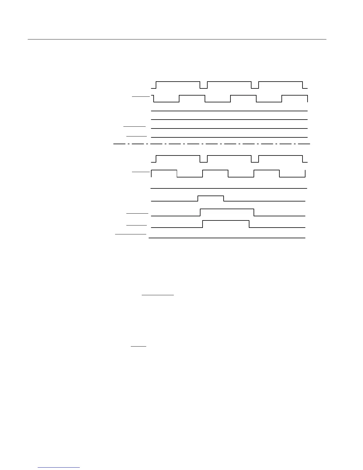
COMP SYNC
H SYNC
LIN SEL EN
LISEL
LIN STRB
PIXSTRB
H LIN SEL EN
COMP SYNC
H SYNC
LIN SEL EN
LISEL
LIN STRB
PIXSTRB
(HIGH)
(LOW)
a.
b.
Figure 4-5: Elements for line select timing: a) Line select off. b) 2-field line
select.
A one-field trigger can be used, in normal configured instruments, by pulling the
REMOTE 1LIN-1FLD
input low to turn on Q821. Turning on Q821 shuts off
Q806 and allows C906 to discharge. The resulting low input on pin 19 of U535
switches the V SYNC pulse output to U535 pin 14 to trigger the Sweep
Generator at the field rate.
V TRIG is the field rate trigger signal enabling the Sweep Generator, which is
positive edge triggered. Field 1 or Field 2 sweep triggering is selected by the
FLD1/FLD2
control line from the processor. A positive edge is output at the
start of the selected field.

 Loading...


