4: Pulse card concepts Model 4200A-SCS Pulse Card (PGU and PMU)
4-18 4200A-PMU-900-01 Rev. B March 2023
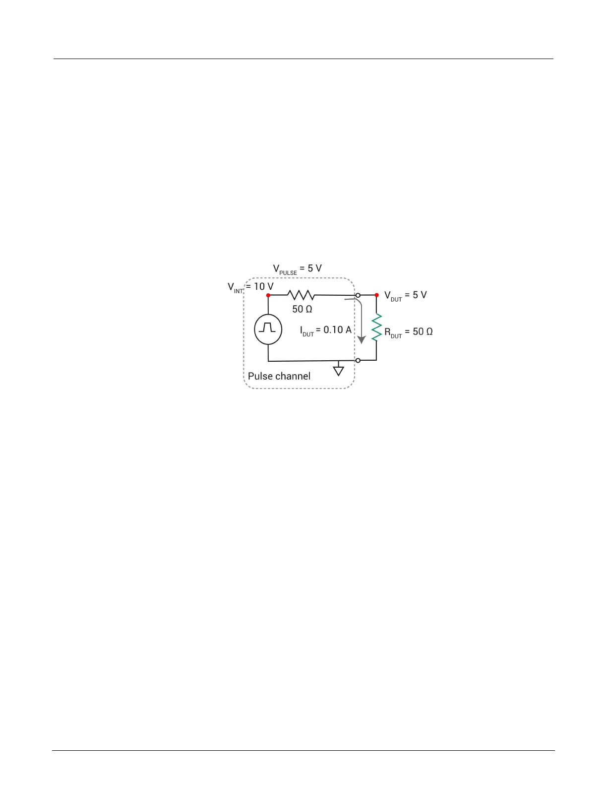
The 50 Ω output resistance of the pulse channel and the DUT resistance effectively make a voltage
divider. Ohm’s law is the only concept required to determine I
DUT
and V
DUT
in this simple nondynamic
approach. Calculate the current, and then use the current to calculate the voltage across the DUT.
Example 1: Ideal situation (50 Ω DUT)
The ideal situation (50 Ω DUT) is shown in the figure below.
HIGH
Figure 88: 5 V pulse into a 50 Ω DUT load
Example 1, showing a 5 V pulse into a 50 Ω DUT load.
V = I * R (Ohm’s Law)
Calculate the current, I
DUT
:
I
DUT
= V
TOTAL
/R
TOTAL
= V
INT
/ (50 Ω + 50 Ω) = 10 V / 100 Ω = 0.1 A
Note that the internal voltage, V
INT
, is 2 times the requested 5 V, so that V
DUT
= 5 V. The 2 times
multiplier is the default case, where:
R
DUT
= Pulse Load = 50 Ω
Pulse load is a channel-based parameter that allows the pulse generator to calculate the value of the
multiplier to source the proper voltage to provide the desired pulse level for the supplied value of the
pulse load. Whenever the value for pulse load does not equal the actual DUT resistance, the voltage
across the DUT will not match the programmed voltage level.
Calculate V
DUT
:
V
DUT
= I
DUT
* R
DUT
= 0.1 A * 50 Ω = 5 V.
 Loading...