8: Testing flash memory Model 4200A-SCS Pulse Card (PGU and PMU)
8-8 4200A-PMU-900-01 Rev. B March 2023
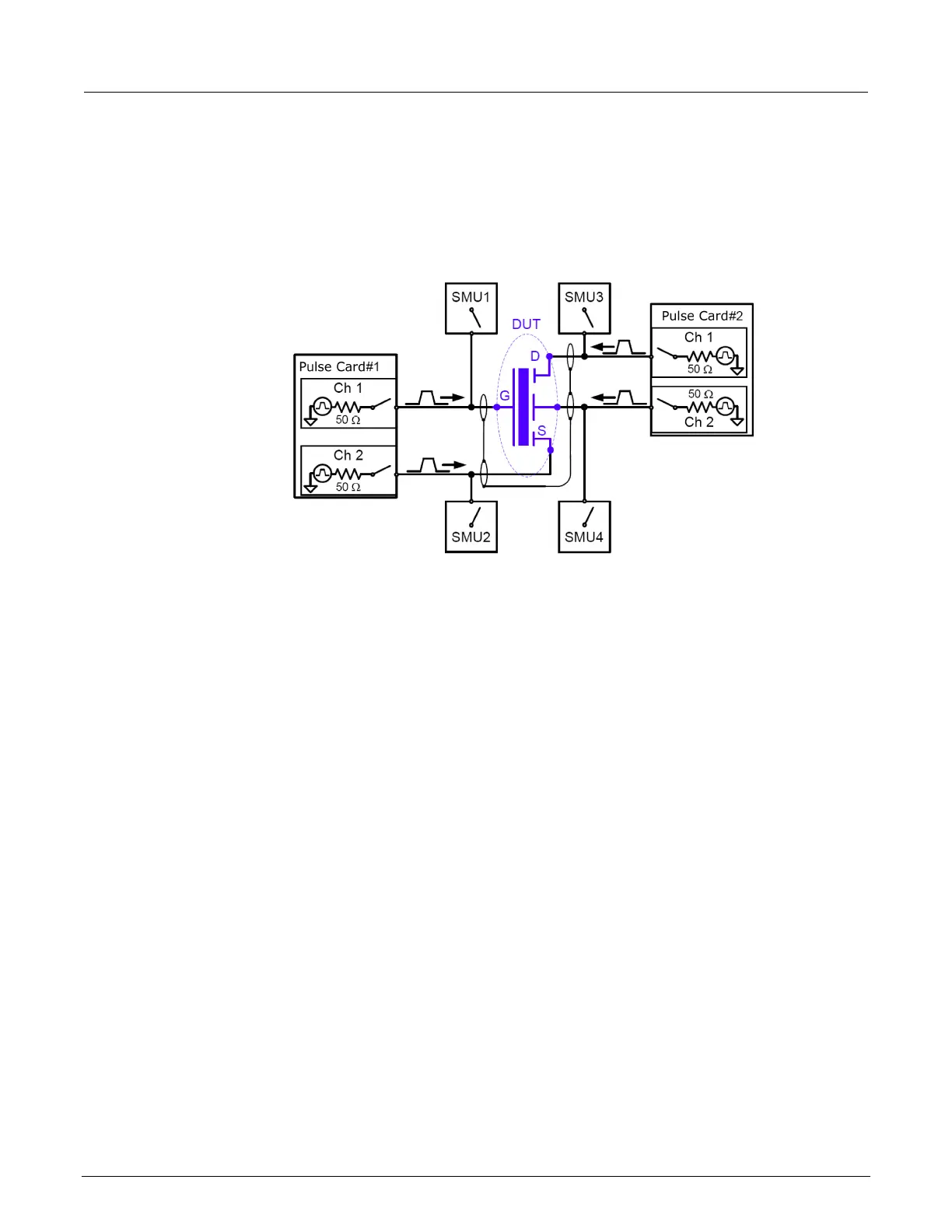
The block diagram for the flash setup is shown in the following figure. To reconfigure from the pulse
stress to dc measure phases, activate the switches on the SMU and pulse cards. During the pulse
program/erase phase, the relays in the pulse channels are closed and the relays in the SMUs are
open. For the dc measure phase, the opposite is true.
Figure 161: Basic schematic of flash testing without a switching matrix
Endurance testing
Endurance testing stresses the DUT with a number of Program+Erase waveform cycles, and then
periodically measures both the voltage threshold in the programmed state (VTP) and the voltage
threshold of the erased state (VTE). These tests to determine the lifetime of the DUT, based on the
number of Program+Erase cycles withstood by the device before a certain amount of shift, or
degradation, in either the VTP or VTE. The endurance test is performed a set number of program and
erase cycles while periodically measuring V
T
for both the programmed and erased state.
The following figure shows typical degradation on a NOR cell for both VTP and VTE as the number of
applied program/erase cycles increases.
 Loading...