2: Connections Model 4200A-SCS Pulse Card (PGU and PMU)
2-6 4200A-PMU-900-01 Rev. B March 2023
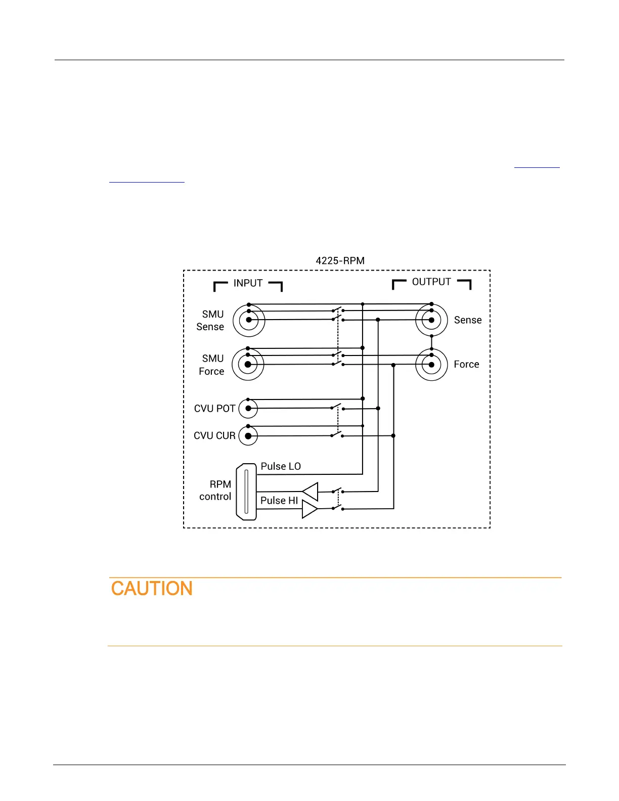
RPM wiring diagram
The internal wiring diagram of the RPM is shown in the following figure.
Signals from the 4200A-SCS instrument cards are routed through the RPM to the output Force and
Sense connectors. Switching is used to control which card is connected to the output. See
Using the
RPM as a switch (on page 2-9) for more information on switching.
The LEDs on the top panel (see the previous figure) indicate which card is connected to the output.
By default, the RPM (pulse mode) is connected to the output unless a SMU or CVU is switched in.
Figure 5: Wiring diagram of the RPM
Connecting the RPM to the PMU
Turn off the system and disconnect the power cord before connecting or disconnecting the
RPM to or from the PMU. Failure to do so may result in RPM or PMU damage, possibly
voiding the warranty.
 Loading...