8: Testing flash memory Model 4200A-SCS Pulse Card (PGU and PMU)
8-2 4200A-PMU-900-01 Rev. B March 2023
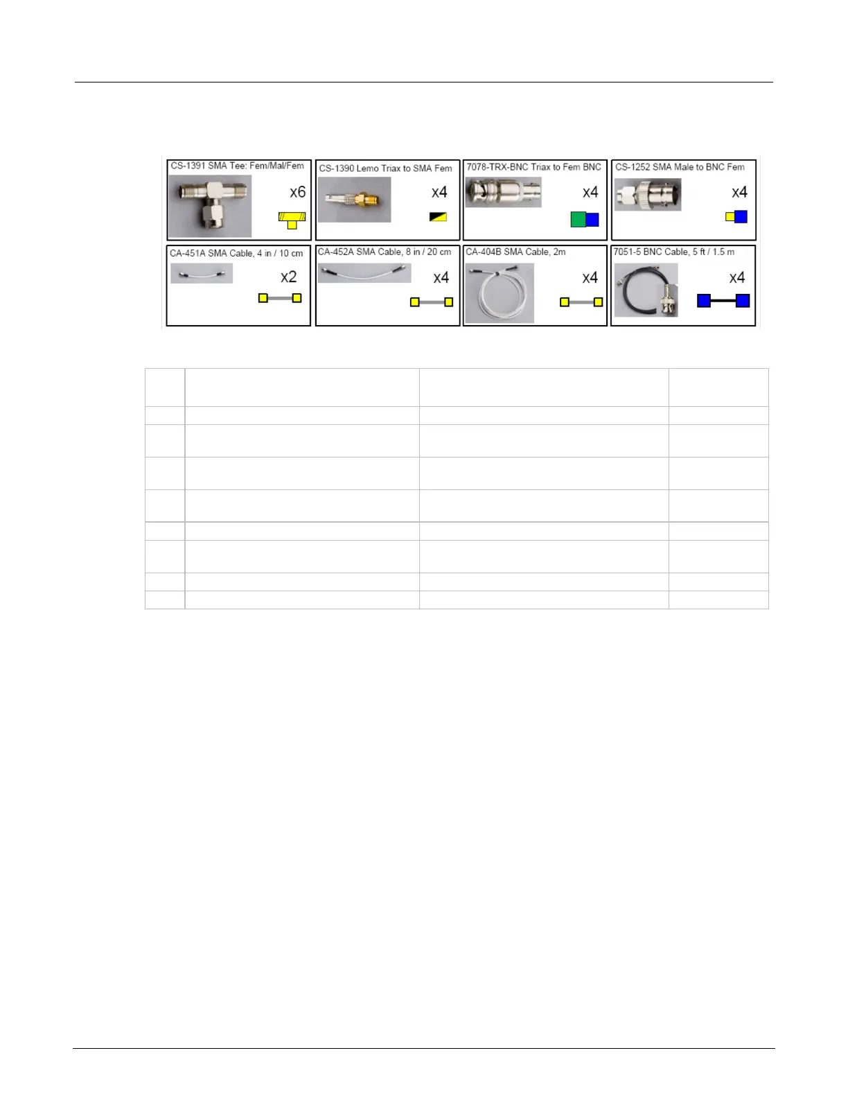
Figure 152: Recommended parts for flash memory testing
Recommended interconnect parts for flash memory testing
Qty. Description Comment
Keithley part
number
SMA tee, female – male – female
Trigger, combine SMU and pulse channels
LEMO triaxial to SMA adapter
Adapt SMU Force output to SMA for signal
interconnect
3-slot male triaxial to female BNC
adapter
Convert BNC cabling to triaxial for prober
or switching matrix connection
SMA male to BNC female adapter
Adapt Tee to BNC for cabling from
instrument to probe manipulators
10.8 cm (4.25 in.) white SMA cables
Interconnect for triggering
20.3 cm (8 in.) white SMA cables
Interconnect between pulse card and SMU
signals
2 m (6.6 ft) white SMA cables
Connect to probe manipulators
This configuration permits independent source and measure for each terminal in a typical 4-terminal
floating gate transistor.
Flash connection guidelines
All interconnects on instrument chassis are white SMA cables. Cables from the instrument to device
are BNC coaxial, except for the direct SMU4 connection, which is black triaxial. Use triaxial to BNC
adapters (if necessary) to connect to probe manipulators.
The trigger interconnects are white SMA cables. Cables from the instrument to device are BNC
coaxial for the pulse card channels and triaxial for the SMUs. Use triaxial to BNC adapters (if
necessary) to connect to probe manipulators.
To test on-wafer devices, there are various ways to connect the SMA cables to the probe
manipulators. For the direct connect method or switch method, adapters convert the BNC cabling to
the triaxial connector to be compatible with many types of probe manipulators.
Use the supplied torque wrench to tighten each connection as it is assembled. Always connect and
torque adapter/cable assemblies before attaching the assembly to the instrument cards.
 Loading...