2: Connections Model 4200A-SCS Pulse Card (PGU and PMU)
2-4 4200A-PMU-900-01 Rev. B March 2023
Prober chuck connections
When possible, avoid pulse connections to the prober chuck. If unavoidable, use these guidelines
when connecting to the prober chuck:
• When making connections to the back side of the wafer, PMU functionality will be diminished.
Use caution and verify waveforms.
• Generally, the chuck adds capacitance and noise. This reduces both low-current and high-speed
sampling performance.
• If one of the device terminals is the back side of the wafer, then pulse only on that terminal (on
chuck) and measure at another terminal using the second channel. If possible, do not measure
from the PMU channel connected to the chuck.
• For a two-terminal device, refer to Two-terminal device connections (on page 2-10), using figure
"Two-terminal device connections to a PMU using both channels" as a guide.
• For a four-terminal device, use the Four-terminal device connections (on page 2-13) to two PMUs
figure, or the Local sensing (on page 2-17) four-terminal figure as a guide (as applicable). This
cabling approach permits the low-side measurement approach described in PMU capacitive
charging/discharging effects (on page 3-35).
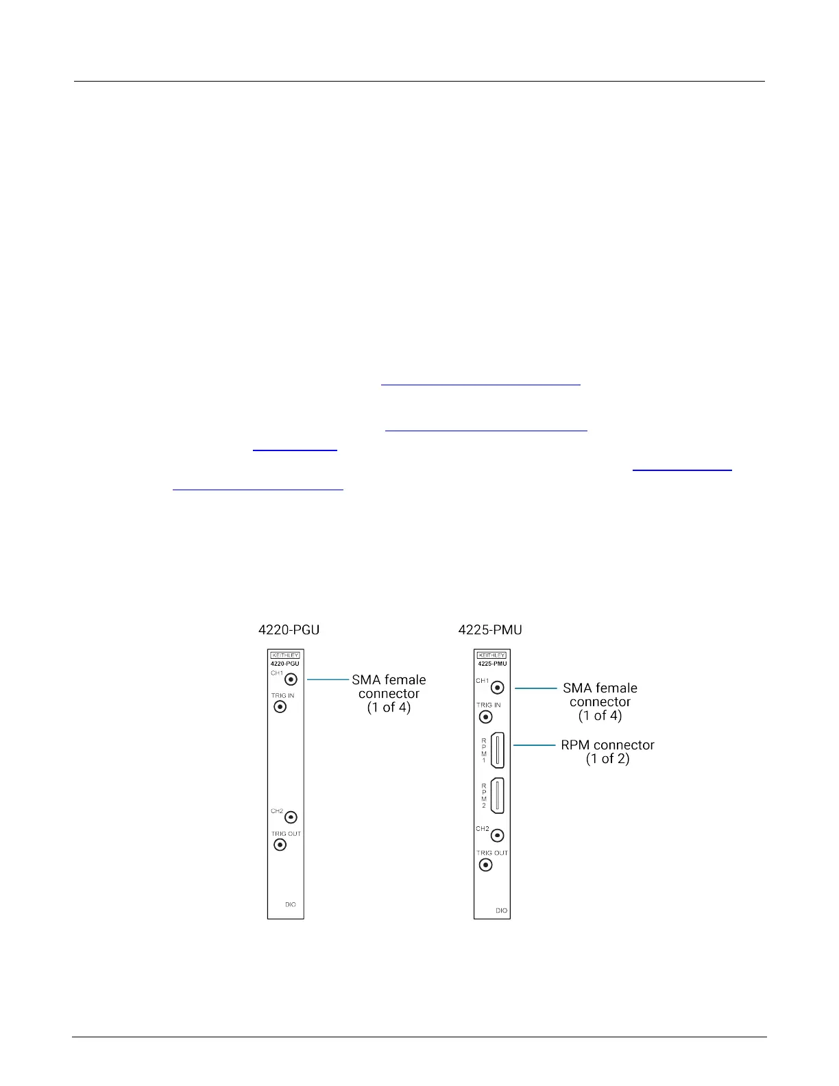
PGU and PMU connectors
The connectors for the PGU and PMU pulse cards are shown in the following figure.
Figure 3: 4220-PGU and 4225-PMU connectors
 Loading...