-SCS Pulse Card (PGU and PMU) User's Manual Section 2:
4200A-PMU-900-01 Rev. B March 2023 2-9
Using the RPM as a switch
You can use the RPM to switch a PMU, CVU, or SMU to a DUT terminal. The RPM wiring diagram
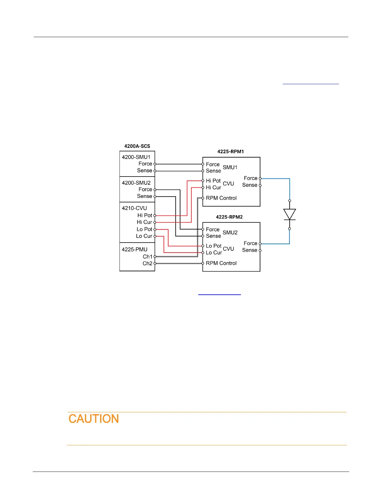
(on page 2-6) figure shows the switches. The following figure shows a typical test configuration for
using an RPM as a switch for a PMU, SMU, and CVU. In general, one RPM per device terminal is
recommended. By default, the PMU (with RPM) is connected to the output unless a SMU or CVU is
switched in.
Figure 9: Test configuration for using RPM as a switch
Both the red cables (supplied with the CVU) and the blue cables (supplied with the optional
4210-MMPC cable kits) are 100 Ω. You can do remote sensing (on page 2-18
) using the optional
4210-MMPC cable kits with the RPMs.
Control RPM switching
Before using an RPM, configure the 4200A-SCS by doing the steps in “Update the RPM
configuration” in Model 4200A-SCS Setup and Maintenance. This properly associates the instruments
connected to each RPM.
There are two methods to control RPM switching:
• ITM operation using automatic switching (after doing the steps in “Update the RPM
configuration”)
• UTM testing from within the user module, use the LPT function rpm_config
You must update the RPM configuration in KCon before using the RPM to control switching.
If you do not, corrupt test data may result due to incorrect switch settings in the RPM.
 Loading...