2: Connections Model 4200A-SCS Pulse Card (PGU and PMU)
2-2 4200A-PMU-900-01 Rev. B March 2023
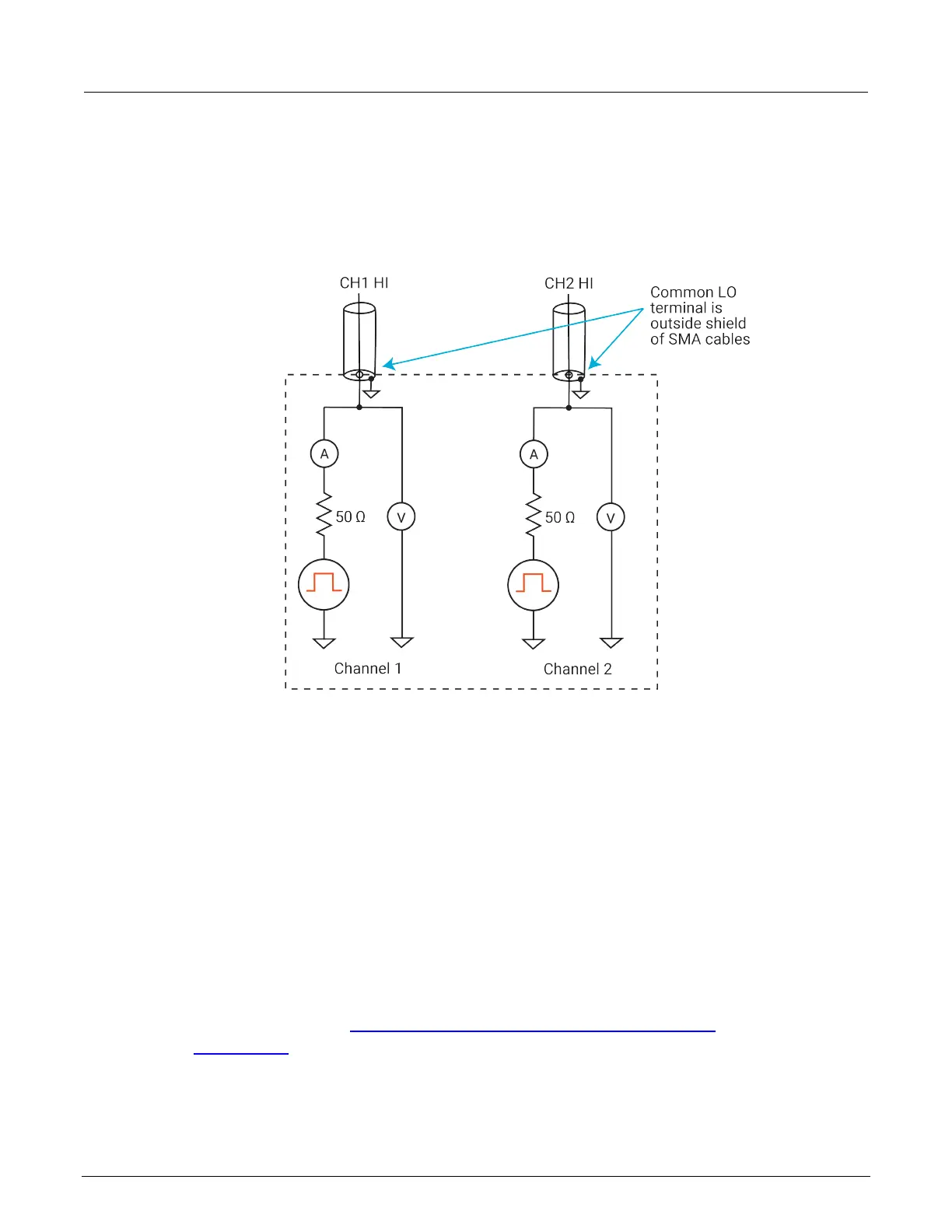
PMU common connections
Common LO for the PMU is the outer shells of the two SMA connectors. With an SMA cable
connected (see following figure), common LO is the outside shield of the cable.
Figure 2: PMU common low terminals
Because pulsing requires high frequency signal propagation, reduce cable inductance by minimizing
the loop area of the connection to the device under test (DUT).
Do not use the GNDU as common low for the PMU to avoid creating a large loop area. When using
the GNDU, an inductive loop area is created when the HI and LO leads are separated. Fast rise times
(dt), high current (di), and large inductances (L) can cause voltage overshoots, oscillations, and
ringing in the high-speed measurement circuit. This is based on Lenz’s law: V = L di/dt.
Shield connections
For multiple PMU channels, you should connect the shields (common LO) from all PMU channels as
close as possible to the DUT. You reduce inductance by minimizing the loop area of the shield
connections. The figure in Using an adapter cable to connect pulse card to DUT (on page 2-16) and
the Local sensing (on page 2-17) figures illustrate proper shield connection schemes using the
supplied cabling.
 Loading...