2: Connections Model 4200A-SCS Pulse Card (PGU and PMU)
2-28 4200A-PMU-900-01 Rev. B March 2023
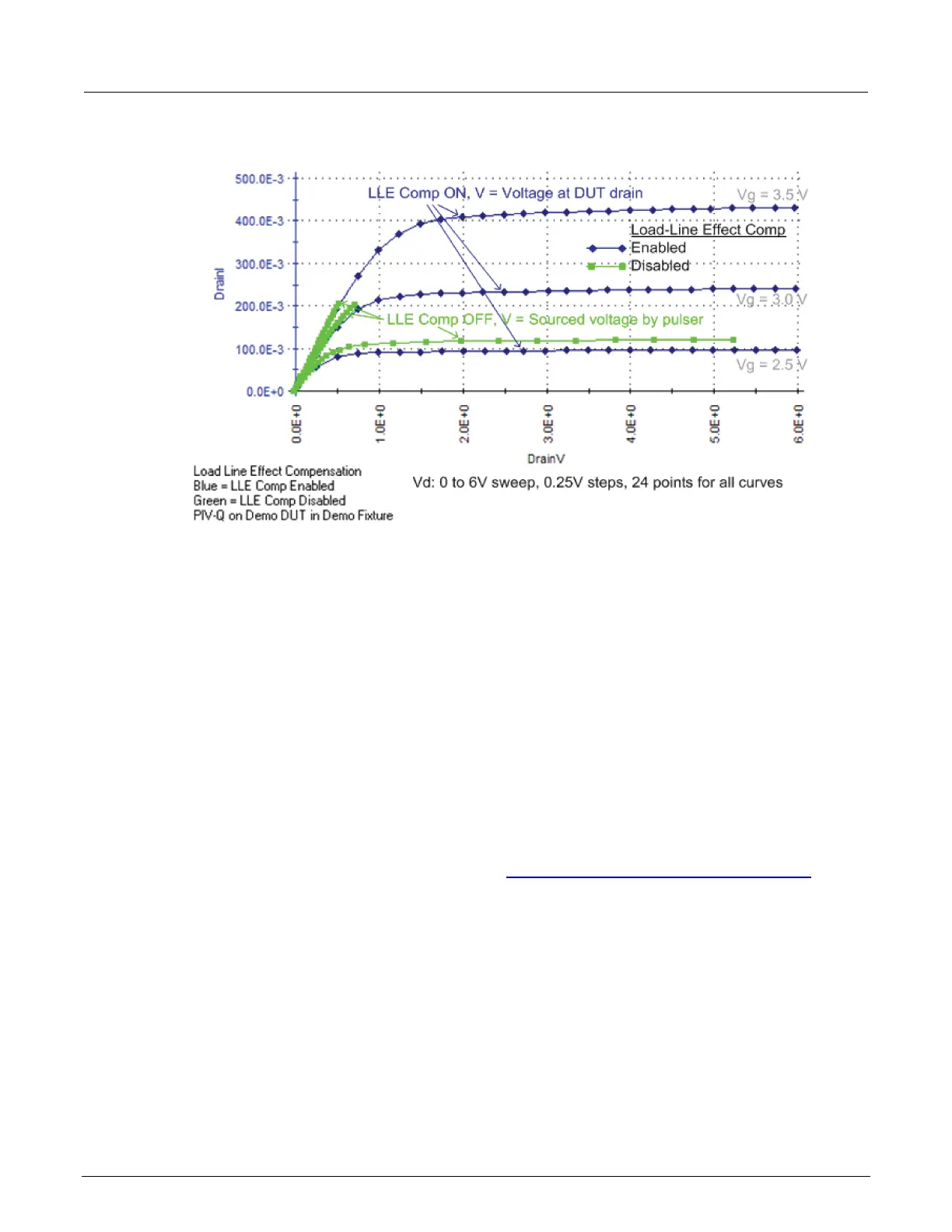
Figure 24: Load-line effect on FET family of curves
The same sweep is used to generate the green curves (LLEC off). The best green curve is the one at
the bottom (bias V
g
= 2.5 V). However, load-line effect prevents the PMU from sourcing 6 V to the
DUT and the 24 pulse-measure points are not evenly spaced. Modifying the sweep to 0 to 6.5 V will
ensure that at least 6 V is output to the DUT, but voltage spacing will still be uneven. The green
curves for the other two bias voltages (V
g
= 3.0 V and 3.5 V) are even more adversely affected by
load-line effect.
Test considerations
The magnitude of the pulse steps affects overall test time. Wider pulses, a higher number of pulses,
and larger voltage steps at each sweep point, all increase the amount of time required for the LLEC
algorithm at each sweep point, which lengthens the overall test time.
There may be some high-gain devices that will not test properly with LLEC enabled. In this case, you
can disable LLEC. To disable LLEC in ITMs, see Disable LLEC and set the output impedance
(on
page 2-30). For UTMs, see the pulse_meas_sm and pulse_meas_wfm functions.
 Loading...