2: Connections Model 4200A-SCS Pulse Card (PGU and PMU)
2-8 4200A-PMU-900-01 Rev. B March 2023
Mounting the RPM
When mounting the 4225-RPM, make sure that there is a minimum of 5 cm (2 in.) of space
between multiple RPM base assemblies. Spacing multiple 4225-RPM or 4200-PA instruments
closer than 5 cm (2 in.) from the 4200-MAG-BASE can cause the internal relays
to malfunction.
RPM diagrams for local and remote sensing
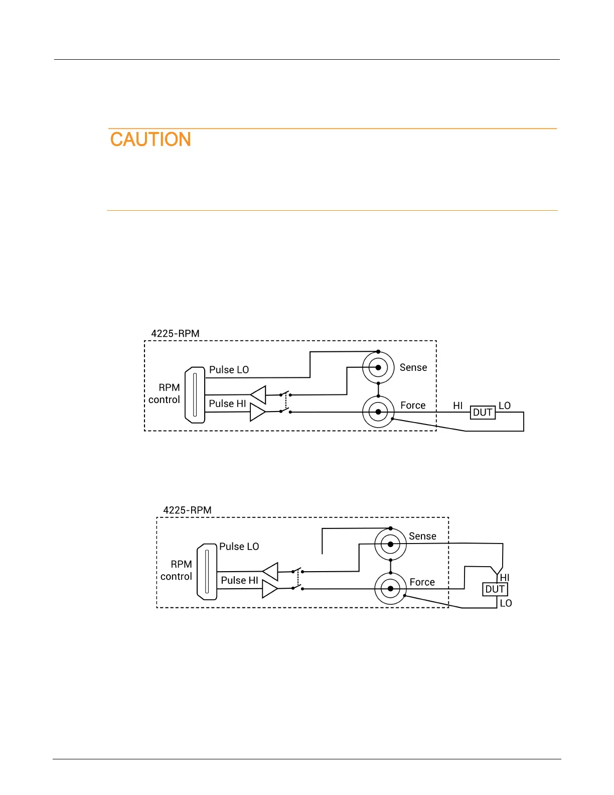
The following figure shows the diagram for local sensing. The center conductor of the Force triaxial
connector is connected to the high side of the device under test (DUT) while the outer shield is
connected to DUT LO. The Sense connector is not used.
Figure 7: RPM wiring diagram for local sensing
The following figure shows the diagram for remote sensing. Both Sense and Force are connected to
DUT HI.
Figure 8: Diagram for remote sensing
 Loading...