-SCS Pulse Card (PGU and PMU) User's Manual Section 4:
4200A-PMU-900-01 Rev. B March 2023 4-17
Waveform capture
The maximum number of rows that can appear in the Analyze sheet for an ITM is 4096. Each
waveform sample uses one row of the sheet. Therefore, the number of samples acquired for a
waveform must fit within the 4096 points.
The number of samples (rows) for a waveform that is 20.48 µs wide is calculated as follows:
Number of samples (rows) = Sample rate x waveform width
= 200e6 x 20.48 µs
= 4096
If the waveform is any wider, the sample rate is automatically lowered by Clarius to fit the waveform
within the 4096 points.
Waveform width that is sampled includes pulse rise, pulse magnitude, pulse fall, and a small portion
of the base level before the rise and after the fall.
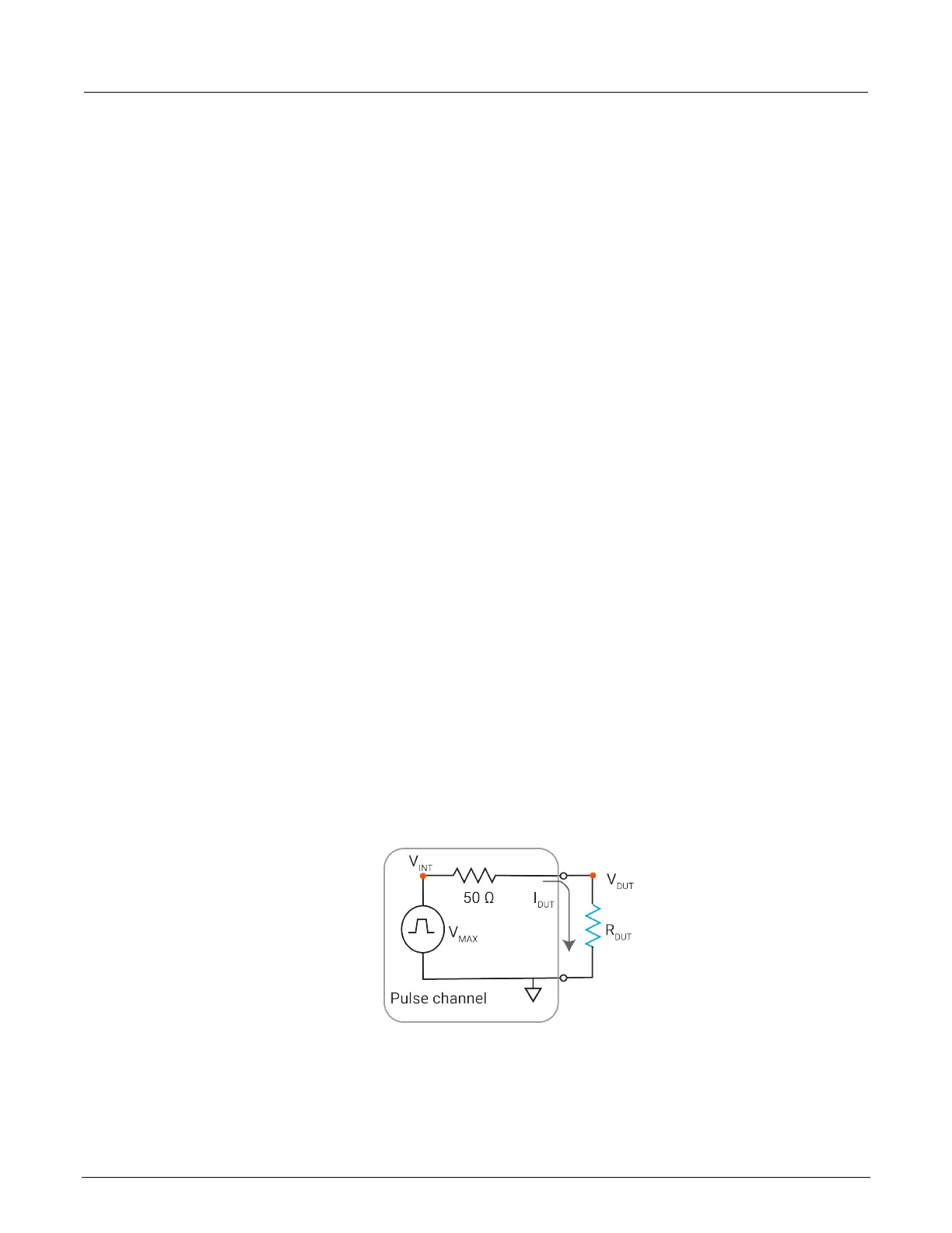
DUT resistance determines pulse voltage across DUT
Each output channel of the 4220-PGU pulse card is effectively a voltage source with a series 50 Ω
resistance. While PMUs have measurement capability, the 4220-PGU pulse card does not, so the
actual voltage across the device under test (DUT) is directly related to the DUT resistance.
There are many output effects that are part of using a pulse generator. This section covers the most
common issue, which is the voltage across the DUT not meeting initial expectations.
There is more than one way to explain the effect of impedance on the DUT voltage. The approach
used below relies on dc concepts and explains the settled portion of the pulse and does not require
knowledge or use of RF concepts. RF concepts are necessary to explain time-based effects, such as
rise time, overshoot, ringing, and reflection.
Figure 87: Schematic of pulse channel and connected DUT
As shown in the figure, the voltage across the DUT, V
DUT
, is directly related to the resistance R
DUT
.
The discussion here is simplified, including resistive impedances only.
 Loading...