-SCS Pulse Card (PGU and PMU) User's Manual Section 3:
Setting up PMUs and PGUs in Clarius
4200A-PMU-900-01 Rev. B March 2023 3-35
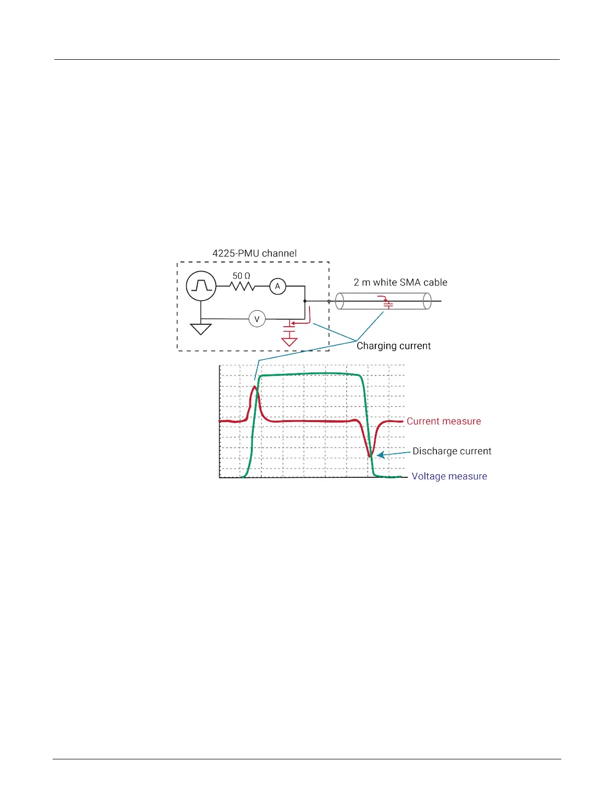
PMU capacitive charging/discharging effects
During pulse transitions, the measured current charges and discharges the capacitance in the system
(see following figure, red waveform). This system capacitance consists of the cable capacitance,
PMU (with RPM, if connected) capacitance, and device capacitance. The following figure shows the
pulse waveform showing capacitive charging and discharging current waveform in relation to the
applied voltage waveform of the PMU connected to the supplied 2 m (6.5 ft) SMA cable (no DUT
connected).
Figure 65: Capacitive charging and discharging
The setup used to generate these waveforms is shown in the previous figure, and also shows the
capacitance and the charging effect (red arrows) seen during pulse transitions. This setup shows a
single channel of a PMU, with the supplied 2 m (6.5 ft) white SMA cable connected to the channel
output. Note that the other end of the SMA cable is open (no connection).
The current shown in the previous figure is measured by the PMU, but is not flowing through a device
under test (DUT). The measured current is the sum of this charging or discharging current, as well as
the current flowing through the DUT. This current is primarily caused by the capacitance in the cable
and is described by the following equation:
I = C * dV/dt
Where:
• I is the measured current
• C is the capacitance
• dV/dt is the pulse voltage amplitude divided by the rise (or fall) time
 Loading...