SERVICE 5-36 Manual 0-4691
5
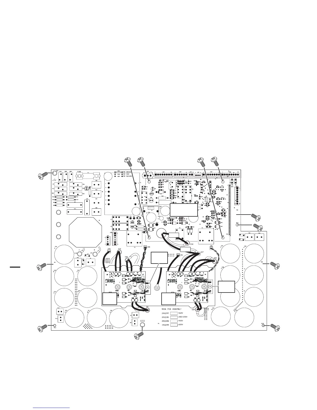
E. Main PC Board Replacement
Follow the antistatic procedures provided with the replacement part.
1. Remove the power supply cover per Section 5.09-A.
2. Remove the Logic PC Board.
3. Remove the POT/LED PC Board.
4. Disconnect all wire and cable connections to the Main PC Board, including the connections from the three smaller PC
Boards. Refer to the Main PC Board Wiring Diagrams in the Appendix pages if necessary.
5. Remove the two long Transformer screws securing the Auxiliary Transformer to the Center Chassis.
6. Remove the other screws securing the PC Board to the Center Chassis.
7. Carefully remove the original PC Board.
8. Install the replacement PC Board by reversing steps above. It may be easier to install the PC Board if the Power Supply
is turned on its right side first. Torque the screws to 17 inch-pounds (1.9 Nm).
E2
E3
E1
Secondary
Transformer
#32
#27
Art # A-04648
IGBT
PCB
IGBT
PCB
IGBT
Module
IGBT
Module
Logic Board
Not Shown
9. Reconnect all wiring. Refer to the Appendix pages in this manual for wiring details.