EasyManua.ls Logo

Tomberlin 2010 E-Merge - User Manual

Tomberlin 2010 E-Merge
151 pages
Print Icon
To Next Page IconTo Next Page
Loading...
TOMBERLIN®CONSUMERDISCLAIMER
Tomberlin®reservestherighttochangethesuggestionsgainedinthisconsumersupportsite.Itis
intendedprimarilyforeducationalpurposesonly.Someexperiencedconsumersprefertodothe
maintenanceandservicethemselves,forthe"DoItYourself"owners,Tomberlinstronglyencourages
interactionwithyourlocaldealerfirstandtoneverattemptaprocedureyouareunfamiliarwithsafely
performing.Anelectricvehiclehasasignificantvolta gethatcanresultinshock,fireandinjuryifnot
performedbyaprofessional.Damagetothevehiclecanalsooccur.Someproceduresrequir especific
torquesettingsthatwhennotfollowedcanresultindangerous,possiblylifethreateningsituations.
Manyerrorswillnotsurfaceimmediately.Theinformationhereinhasgenerallyproventoenhancethe
lifecycle,safetyandoverallownershipexperiencewhenproperlyfollowed.Tomberlinassumesno
liabilityforthecontentprovidedinthisconsumereducationalsectionanditispossiblethatanerror
withregardtospelling,grammar,nomenclature,andtranslationispresent.Notethattheinformation
providedshouldbetreatedaslivedocumentsmeaningtheyarealwaysinastateofrefinement,
correctionandimprovement.Checkbackoftenandifprinted,checkbackpriortoreliancetoassurethey
remaincurrent.Neverattempttomanipulatethevehicletoexceedthespeedasrequiredby
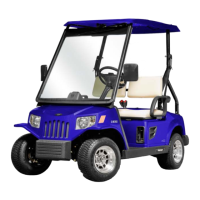
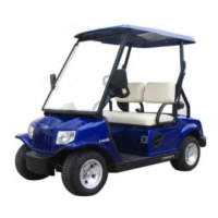
regulations.ThehighestspeedrangeforTomberlin®EMerge™PTV'sandLSV'sarefactorysetat1519
mphasaPTVor2225mphasanLSV.Consumersshouldalwaysexerciseprudentcommonsense
measures,usepropersafetygearwithtoolsdesignedspecificallyforthetask.Alwaysutilizeinsulated
toolsaroundelectricalconnections.Neverexceedyourcomfortlevelandwhenindoubt,stopandcall
yourlocaldealer.TomberlinAuthorizedDealersarealwaysyourbestresource.Ifyounoticeanerroror
haveanideathatwillimproveoureffortshere,pleaseemailyourideatoinfo@tomberlin.net.

Table of Contents

Questions and Answers

  • J
    Jamie CaseySep 23, 2025
    What does RELAY DRIVER ON mean on my Tomberlin Offroad Vehicle?
    • A
      Amanda HinesSep 23, 2025
      If your Tomberlin Offroad Vehicle displays 'RELAY DRIVER ON', it means the time-delay coil has less currency. This could be because the time-delay coil is off or damaged.
  • P
    Paul RandallAug 23, 2025
    What to do if my Tomberlin Offroad Vehicle shows MOTOR STALL?
    • K
      Kimberly JonesAug 23, 2025
      If your Tomberlin Offroad Vehicle shows 'MOTOR STALL', it indicates a motor failure. This may be due to incorrect motor installation, motor stall, EM brake cable fault, or a broken speed sensor. Check these potential issues.
  • K
    Kyle MitchellAug 25, 2025
    What to do if my Tomberlin 2010 E-Merge displays CIRCUIT BRKR OPEN?
    • A
      Andrew MannAug 26, 2025
      If your Tomberlin Offroad Vehicle displays 'CIRCUIT BRKR OPEN', it means the antislip circuit is open or the fuse is damaged. Check if the fuse is broken, if there is an antislip circuit failure, or if the speed sensor has failed. These are the suggested solutions.
  • C
    Charles WhiteheadAug 27, 2025
    What to do if my Tomberlin 2010 E-Merge Offroad Vehicle displays SPEED SENSOR FAULT?
    • J
      Jose CainAug 27, 2025
      If your Tomberlin Offroad Vehicle displays 'SPEED SENSOR FAULT', it indicates a speed sensor failure. This could be due to no connection on the speed sensor or the speed sensor being broken. Check the connection and the sensor itself.
  • B
    briannasimsAug 27, 2025
    What does MAIN WELDED mean on my Tomberlin 2010 E-Merge Offroad Vehicle?
    • C
      christopherowensAug 27, 2025
      If your Tomberlin Offroad Vehicle displays 'MAIN WELDED', it means the main contactor is welded. This can happen if the main contactor is indeed welded or if the drive of the main contactor is shorted. Check these components.
  • B
    Brandi ByrdSep 17, 2025
    What does RELAY COIL FAULT mean on my Tomberlin 2010 E-Merge?
    • A
      allison42Sep 17, 2025
      If your Tomberlin Offroad Vehicle displays 'RELAY COIL FAULT', it indicates a time-delay coil failure, possibly due to a wrong connection on the time-delay coil.
  • S
    Seth HernandezSep 14, 2025
    What does HW FAILSAFE mean on my Tomberlin 2010 E-Merge Offroad Vehicle?
    • T
      Tyler RuizSep 14, 2025
      If your Tomberlin Offroad Vehicle displays 'HW FAILSAFE', it indicates an automatic checking failure, likely due to a broken controller.
  • D
    david68Sep 15, 2025
    What does THROTTLE FAULT 1 mean on a Tomberlin Offroad Vehicle?
    • S
      Samantha CoxSep 16, 2025
      If your Tomberlin Offroad Vehicle displays 'THROTTLE FAULT 1', it means the sliding signal of the accelerator is out of range. This could be due to an open input cable of the throttle or a short circuit in the throttle cable to B+ or B-.
  • J
    Justin JonesSep 6, 2025
    What does CURRENT SENSE FAULT mean on my Tomberlin Offroad Vehicle?
    • V
      Victoria Hawkins DDSSep 6, 2025
      If your Tomberlin Offroad Vehicle displays 'CURRENT SENSE FAULT', it indicates an excitation currency sensor failure. This is likely due to a broken controller.
  • B
    Brandon ReedSep 3, 2025
    What does AUX CONT DN mean on my Tomberlin 2010 E-Merge Offroad Vehicle?
    • P
      Phillip WilsonSep 3, 2025
      If your Tomberlin Offroad Vehicle displays 'AUX CONT DN', it means the auxiliary contactor is open. This can be caused by a short circuit in the driving of the auxiliary contactor.

Summary

TOMBERLIN CONSUMER DISCLAIMER

Chapter 1 Overview

Safety Precautions

Essential safety measures for vehicle maintenance and operation.

Use Appropriate Tools

Guidelines on selecting and using correct tools for maintenance tasks.

Cautions

Important warnings and advice for maintenance procedures.

Chapter 2 Regular Inspection and Adjustment

Regular Maintenance

Schedule and procedures for routine vehicle upkeep.

Periodic Lubrication Plan

Specific points and recommended lubricants for periodic maintenance.

Braking System Inspection

Detailed steps for inspecting and measuring the vehicle's braking components.

Steering System Inspection

Procedures for checking steering wheel play and linkage condition.

Front Wheel Alignment

Steps to measure and adjust the vehicle's toe-in for proper alignment.

Wheel Bearing Inspection

Procedures for inspecting front and rear wheel bearings for wear and play.

Shock Damper Inspection

Method for inspecting shock dampers for oil leaks and spring condition.

Seat Belt Inspection

Steps to check the binding force and buckle security of seat belts.

Chapter 3 Canopy

Canopy Removal

Instructions for removing the vehicle's canopy and associated rods.

Pillar Removal

Steps for detaching the vehicle's pillars for access or replacement.

Chapter 4 Body

Front Bumper Removal

Procedure for removing and installing the front bumper assembly.

Rear Tray and Bumper Removal

Steps for removing the rear tray and rear bumper components.

Seat Cushion and Backrest Removal

Instructions for disassembling and removing seat cushions and backrests.

Dashboard and Front Cover Removal

Procedures for removing the dashboard and front cover panels.

Rear Cover Removal

Steps to remove the vehicle's rear cover and associated components.

Chapter 5 Front Axle

Front Axle Assembly

Exploded view and part identification for the front axle system.

Front Axle Removal and Inspection

Detailed steps for removing, inspecting, and testing front axle components.

Chapter 6 Driving Axle

Driving Axle Assembly

Exploded view and part list for the driving axle system.

Driving Axle Removal and Inspection

Procedures for removing, inspecting, and testing the driving axle and its parts.

Gearbox and Differential Gear Removal

Steps for disassembling and removing the gearbox and differential gear.

Chapter 7 Brake System

Brake System Components

Identification of various brake system parts through an exploded view.

Brake Pedal Inspection and Removal

Procedures for measuring brake pedal free play and removing the pedal assembly.

Parking Brake Handle Inspection

Steps to measure parking brake handle free play and inspect the cable.

Accelerator Pedal Inspection

How to inspect the accelerator pedal's operating condition and free travel.

Chapter 8 Steering System

Steering System Components

Exploded view and list of parts for the vehicle's steering system.

Steering System Removal

Detailed instructions for removing the steering wheel, column, and stalk.

Steering Gear Removal and Disassembly

Procedures for removing the steering gear and its internal components.

Chapter 9 Electric Component

Key Switch Operations

Steps for removing and installing the vehicle's key switch.

Forward;Reverse Gear Switch Operations

Procedures for removing and installing the forward/reverse gear selector switch.

Lighting and Indicator Components

Instructions for removing and installing headlights, tail lights, and indicators.

Motor and Controller Operations

Steps for removing and installing the electric motor and controller unit.

Battery System Components

Procedures for battery removal, installation, and DC converter operations.

Chapter 10 Troubleshooting

Troubleshooting Instructions Part 1

Guide to diagnose and fix common vehicle starting and performance issues.

Troubleshooting Instructions Part 2 (Controller Failure Codes)

Interpretation of controller error codes for diagnosing faults.

Check Procedures Index

List of diagnostic checks for electrical system components.

Chapter 11 Battery and Charger

Battery Overview and Maintenance

Information on battery types, common issues, and preventative maintenance.

Battery Replacement Procedure

Step-by-step guide for safely replacing the vehicle's battery.

Battery Charging and Storage

Instructions for proper battery charging, deep discharge, and storage.

Battery Troubleshooting and Testing

Diagnostic procedures including voltage, hydrometer, and discharge tests.

Battery Charger Operation and Maintenance

Guide to operating, troubleshooting, and maintaining the vehicle's battery charger.

Chapter 12 Electric Motor

Electric Motor Overview and Inspection

General information and external checks for the electric traction motor.

Motor Electrical Circuit Checks

Procedures for testing internal short circuits and open circuits in the motor.

Motor Removal and Disassembly

Steps for removing the motor and disassembling its components like armature and brushes.

Motor Element Inspection and Testing

Detailed inspection of armature, windings, commutator, and bearings.

Motor Assembly and Mounting

Instructions for reassembling the electric motor and mounting it to the axle.

Speed Sensor Inspection and Replacement

Procedures for checking and replacing the electric motor's speed sensor.

Tomberlin 2010 E-Merge Specifications

General IconGeneral
BrandTomberlin
Model2010 E-Merge
CategoryOffroad Vehicle
LanguageEnglish

Related product manuals