RemovingtheBracketfortheAgitation
ThrottleMount
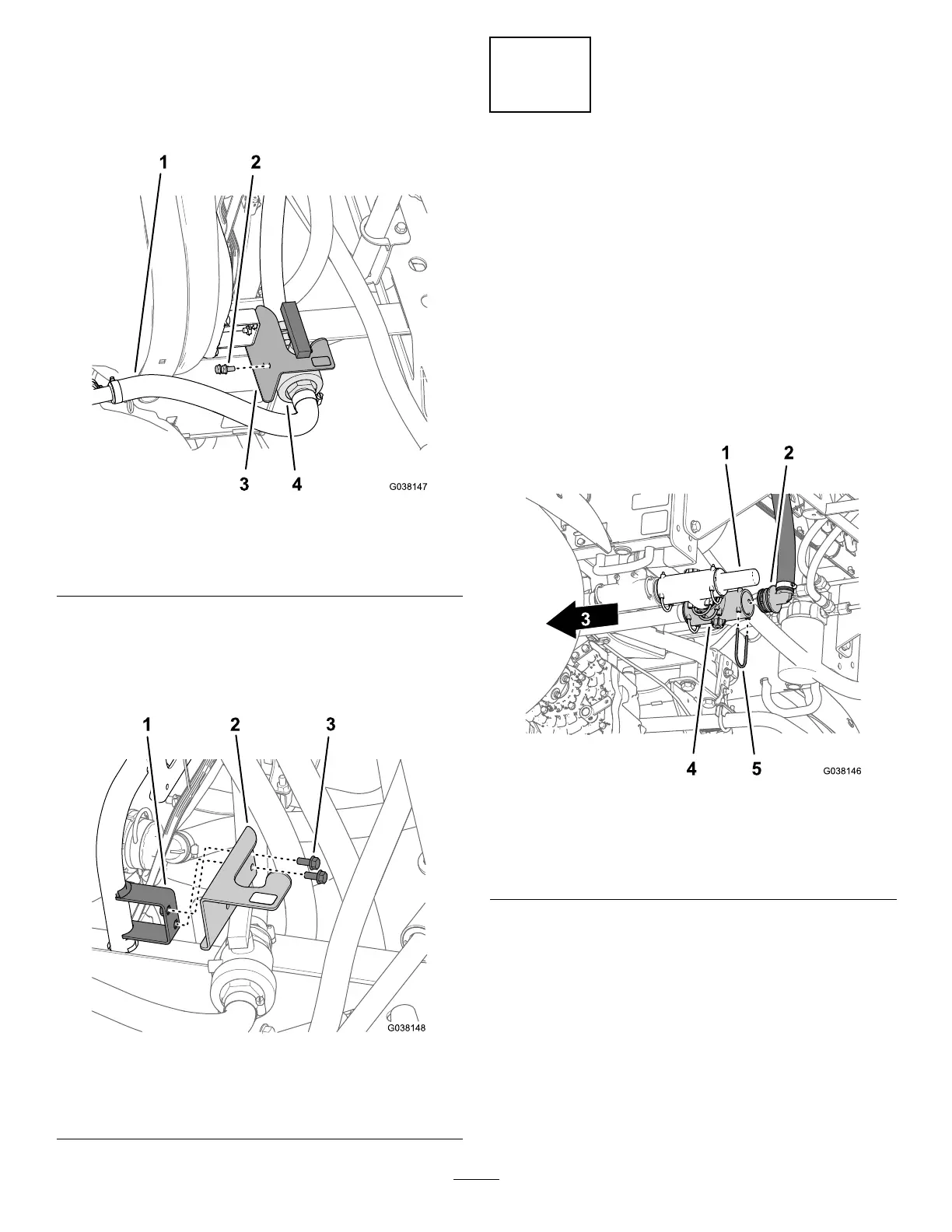
1.Removethe2ange-headbolts(5/16x5/8inch)that
securetheagitationthrottlevalvetothethrottle-valve
bracket(Figure21).
Figure21
1.Agitationsupplyhose
3.Bracket(throttlevalve)
2.Flange-headbolt(5/16x
5/8inch)
4.Agitationthrottlevalve
2.Removethe2ange-headbolts(5/16x3/4inch)that
securethethrottle-valvebrackettothethrottle-valve
mount,andremovethebracket(Figure22).
Note:Younolongerneedthe4ange-headboltsand
throttle-valvebracket.
Figure22
1.Mount(throttle-valve
bracket)
3.Flange-headbolt(5/16x
3/4inch)
2.Bracket(throttlevalve)
7
RemovingtheAgitation,Rate,
andMaster-SprayValves
NoPartsRequired
DisconnectingtheReturn,
Sprayer-Supply,andBypassHoses
1.Atthebackofthemachine,removetheretainerthat
securesthe90°barbedttingofthereturnhosetothe
T-ttinglocatedinboardofthepressure-reliefvalve
(Figure23).
Note:RetaintheretainersforinstallationinInstalling
theReturnHose(page31).
Figure23
1.Pressure-reliefvalve4.T-tting
2.90°barbedtting(return
hose)
5.Retainer
3.Frontofthemachine
2.Removethe90°barbedttingfromtheT-tting
(Figure23).
3.Removetheretainerthatsecuresthe90°barbedtting
ofthesprayersupplyhosetotheT-ttinglocated
forwardofthepressure-reliefvalve(Figure24).
Note:RetaintheretainersforinstallationinInstalling
theSprayerSupplyHose—Machinewithoutthe
OptionalEductorKit(page34).
14

 Loading...


