RemovingtheAgitation-ManifoldValve
1.Removetheclampsandgasketsthatsecurethe
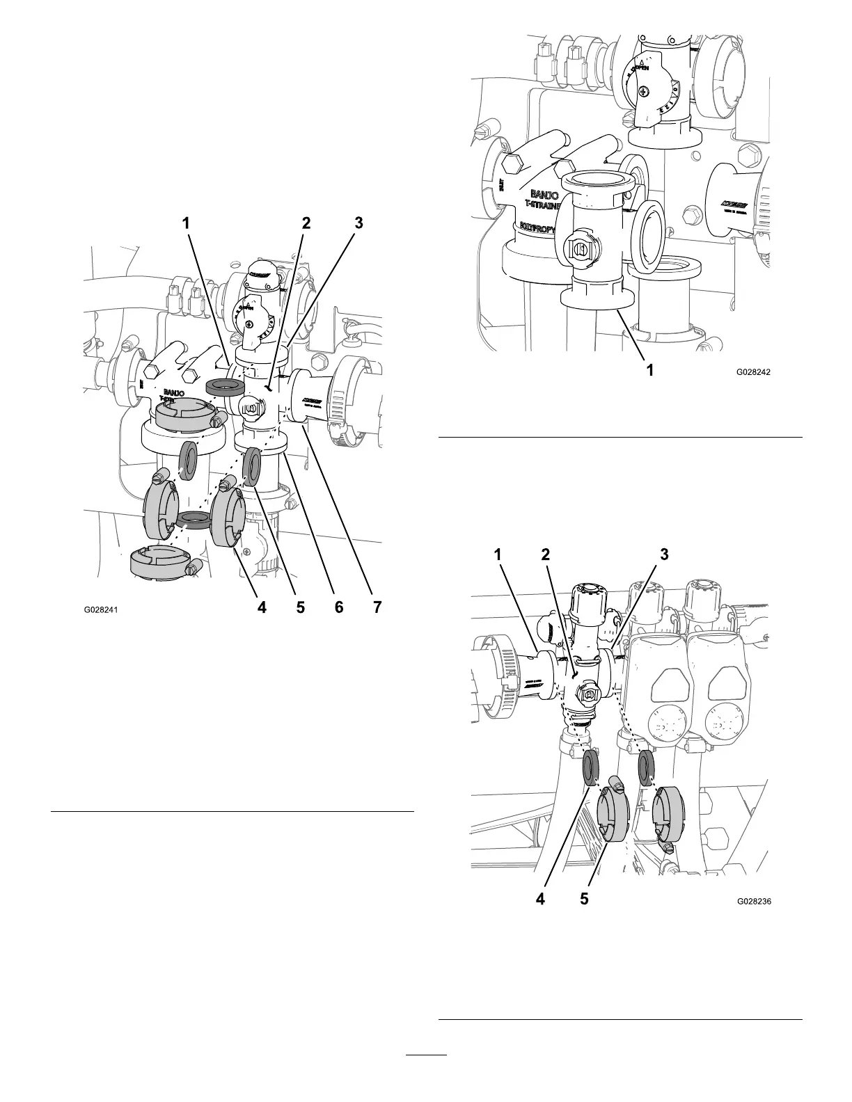
manifoldfortheagitationvalvetotheagitationbypass
valve,pressure-lterhead,reducercoupling,and
adaptertting(agitationthrottlevalve)asshownin
Figure112.
Note:Retaintheclamps,gaskets,quickconnect,and
quick-connectpinforinstallationinInstallingthe
Agitation-ManifoldValve(page57).
Figure112
AgitationValve
1.Flange(pressure-lter
head)
5.Gasket
2.Manifold(agitationvalve)6.Flange(adapter
tting—agitationthrottle
valve)
3.Flange(agitationbypass
valve)
7.Flange(reducercoupling)
4.Flangeclamp
2.Removetheagitation-valvemanifoldfromthemachine
(Figure113).
Figure113
1.Agitation-valvemanifold
RemovingtheSectionValveManifold
1.Removeclampsandgasketsthatsecurethemanifold
forthesectionvalve(Figure114)totheadjacentsection
valve(ifleft,sectionvalveandreducercoupling).
Figure114
1.Flange(reducercoupling)4.Gasket
2.Manifold(sectionvalve)
5.Flangeclamp
3.Flange(adjacentsection
valve)
54

 Loading...


