RemovingtheSectionBypassHose
1.Removetheretainerthatsecuresthe90°barbedtting
ofthesectionbypasshosefortheboom-sectionvalves
fromthebulkheadttingatthebackofthesprayer
tank(Figure28).
Figure28
1.Retainer
3.Bulkheadtting(sprayer
tank)
2.90°barbedtting—section
bypasshose
(boom-sectionvalves)
2.Removethe90°barbedttingfromthebulkhead
tting(Figure28).
Note:RetaintheretainersforinstallationinInstalling
theSectionBypassHose(page37);younolongerneed
thebypasshosefortheboom-sectionvalves.
8
ReplacingtheValveElectrical
Connectors
Partsneededforthisprocedure:
6
Cableties
5
3-pinadapter
14-pinadapter
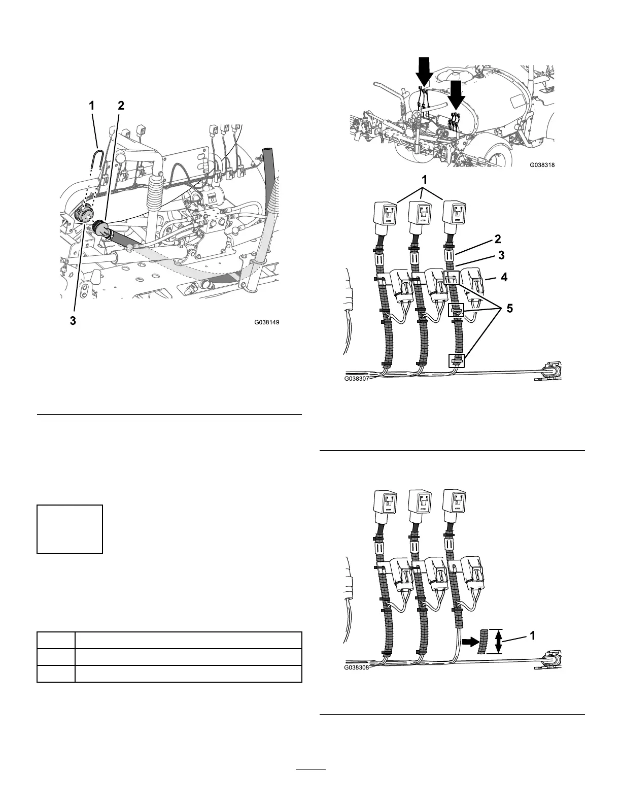
PreparingtheWireHarness
1.Atthebackofthemachine,removethe3tiewrapsthat
securetheconvolutedtubingandinline-fuseblockto
thewireharnessforthebranchlabeledRIGHTSPRAY
VALVEasshowninFigure29.
Figure29
1.DINconnectors
4.Inline-fuseblock
2.Label
5.Cableties
3.Convolutedtubing
2.Remove76mm(3inches)sectionofconvolutedtubing
asshowninFigure30.
Figure30
1.Removedsectionofconvolutedtube—76mm(3inches)
3.Positiontheconvolutedtubingtowardthemainbranch
ofthewireharnessasshowninFigure31.
16

 Loading...


