Figure67
1.Agitationsupplyhose—2.5x72cm(1x28-1/4inches)
3.Assemblethequick-connecttting(straightbarbed)
oftheagitationsupplyhoseontothequickcoupling
oftheagitationthrottlevalvewiththeretainerthatis
suppliedwiththehose(Figure67).
InstallingtheBypassHose—Machines
withouttheOptionalSprayWandKitor
ElectricHoseReelKit
Ifyourmachinehastheoptionalspraywandkitorelectric
hosereelkit,skipthisprocedure.Youwillinstallthebypass
hosein17InstallingtheShutoffValveandHosesforthe
OptionalSprayGunKitorElectricHose-ReelKit(page40).
1.Assemblethestraightbarbedttingofthebypass
hose—2.5x110cm(1x43-1/2inches)intotherear
portoftheT-ttingatthetopofthesprayertank
(Figure68).
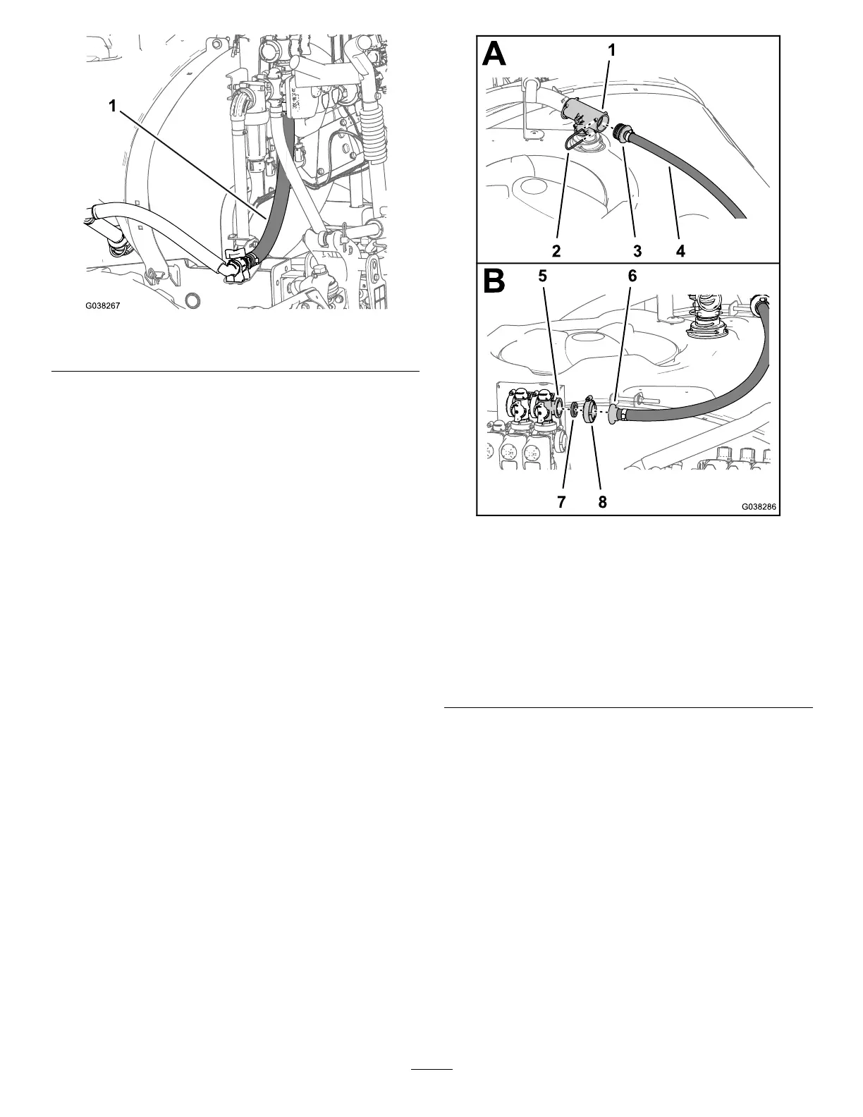
Figure68
1.T-tting
5.Flange—bypassvalve
(master-sprayvalve
position)
2.Retainer
6.Straightbarbedtting
3.Straightbarbedtting7.Gasket—25x35mm(1x
1-3/8inches)
4.Bypasshose—2.5x110
cm(1x43-1/2inches)
8.Flangeclamp—40to
64mm(1-9/16to2-1/2
inches)
2.SecurethestraightbarbedttingtotheT-tting
withtheretainerthatyouremovedinstep5of
DisconnectingtheReturn,Sprayer-Supply,andBypass
Hoses(page14).
3.Routethebypasshosetothebypassvalvelocated
abovethemaster-sprayvalveasshowninFigure69.
33
 Loading...


