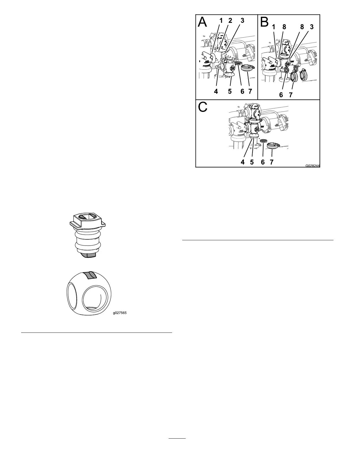
AssemblingtheManifoldValve
1.ChecktheconditionoftheoutletttingO-rings
(sectionvalvemanifoldonly),endcapO-rings,back
seatingO-rings,andballseatfordamageorwear
(Figure118andFigure119).
Note:ReplaceanydamagedorwornO-ringsorseats.
2.Applygreasetothevalvestemandinsertitintothe
valve-stemseat(Figure118andFigure119).
3.Installthevalvestemandseatintothemanifoldand
securethestemandseatwiththestemretainer(Figure
118andFigure119).
4.EnsurethatthebackseatingO-ringandtheballseat
arealignedandseatedintotheend-captting(Figure
118andFigure119).
5.Installtheend-cap-ttingassemblyontothemanifold
bodyuntiltheangeoftheend-capttingtouchesthe
manifoldbody(Figure118andFigure119),thenturn
theend-capttinganadditional1/8to1/4turn.
Note:Usecautiontopreventdamagetotheendof
thetting.
6.Inserttheballintothevalvebody(Figure120).
Note:Thevalvestemshouldtinsidetheball-drive
slot.Ifthevalvestemdoesnott,adjusttheposition
oftheball(Figure120).
Figure120
7.Turnthevalve-stemassemblysothatthevalveisclosed
(Figure117).
8.Repeatsteps4and5fortheotherend-cap-tting
assembly.
InstallingtheAgitation-ManifoldValve
1.Aligntheangeoftheagitationbypassvalve,1gasket,
andtheend-cap-ttingangeoftheagitation-valve
manifold(Figure121).
Note:Ifneeded,loosenthemountinghardwarefor
thepressure-lterheadasneededtoprovideclearance.
Figure121
1.Flange(pressure-lter
head)
5.Gasket
2.Flange(agitationbypass
valve)
6.Quickconnect
3.Flange(reducercoupling)7.Manifold(agitationvalve)
4.Flangeclamp8.Flange
(manifold—agitation
valve)
2.Assembletheagitationbypassvalve,gasket,and
agitation-valvemanifoldwithaclamp,andtightenby
hand(Figure121).
3.Alignagasketbetweentheangesofthepressure-lter
headandtheagitation-valvemanifold(Figure121).
4.Assemblethepressure-lterhead,gasket,and
agitation-valvemanifoldwithaclamp,andtightenby
hand(Figure121).
5.Alignagasketbetweentheangesoftheagitation-valve
manifoldandthereducercoupling(Figure121).
6.Assembletheagitation-valvemanifold,gasket,and
reducercouplingwithaclamp,andtightenbyhand
(Figure121).
7.Alignagasketbetweentheangesoftheagitation-valve
manifoldandtheadapterttingfortheagitation
throttlevalve(Figure121).
8.Assembletheagitation-valvemanifold,gasket,and
adapterttingwithaclamp,andtightenbyhand
(Figure121).
9.Ifyouloosenedthemountinghardwareforthe
pressure-lterhead,tightenthenutandboltto1978to
2542N∙cm(175to225in-lb).
57

 Loading...


