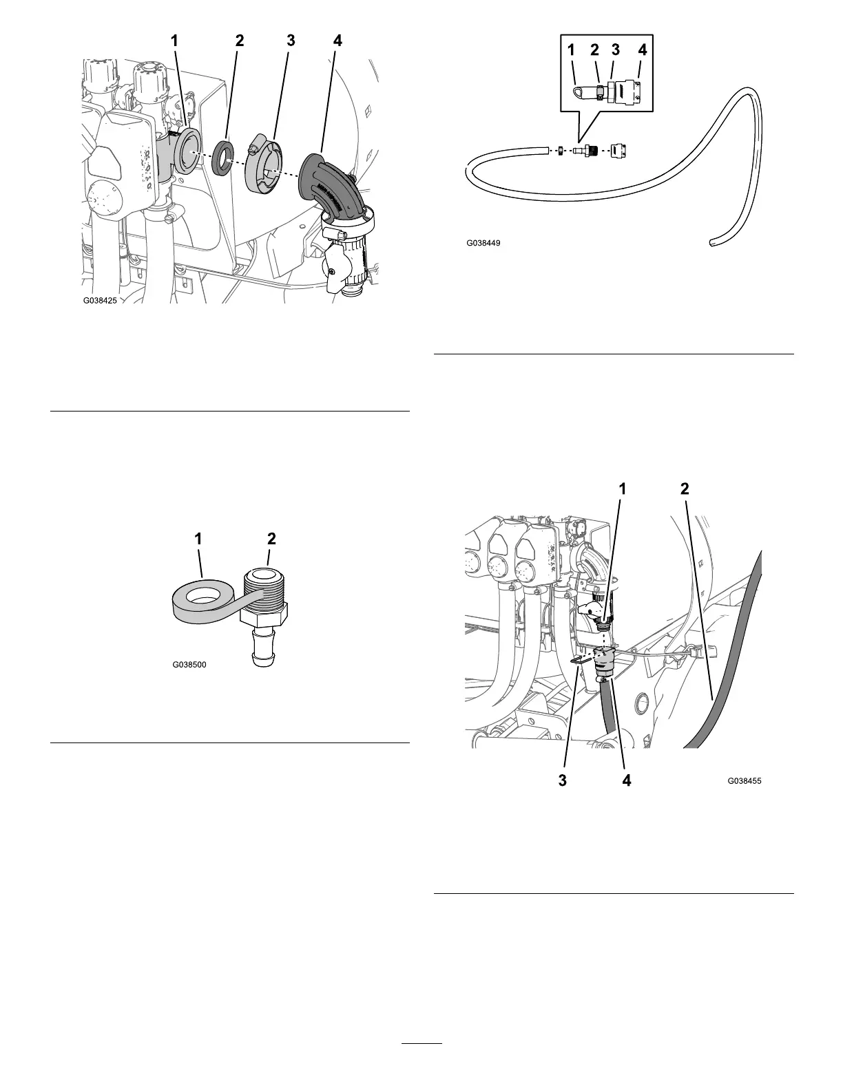
Figure89
1.Flange
(right-boom-sectionvalve)
3.Flangeclamp
2.Gasket4.90°elbow(withpressure
port)
InstallingtheSupplyHose—Machines
withtheOptionalSprayGunKit
1.ApplyPTFEtapetothethreads(Figure91)ofthe
straightbarbedtting(1/2inch).
Figure90
1.PTFEtape
2.Straightbarbedtting(1/2
inch)
2.Assemblethestraightbarbedtting(1/2inch)intothe
quick-connecttting(socket)asshowninFigure91.
Figure91
1.Hose—1.3x762cm(1/2x
300inches)
3.Straightbarbedtting(1/2
inch)
2.Hoseclamp
4.Quick-connecttting
(socket)
3.Assemblethehose—1.3x762cm(1/2x300inches)
withahoseclamp6to11mm(1/4to7/16inch)onto
thestraightbarbedtting(Figure91).
4.Assemblethequick-connecttting(socket)ofthehose
tothequick-connectttingoftheangeshutoffvalve
(Figure92).
Figure92
1.Quick-connecttting
(angeshutoffvalve)
3.Retainer
2.Hose—1.3x762cm(1/2x
300inches)
4.Quick-connecttting
(socket)
5.Securethequick-connectttingsofthehosesandthe
angeshutoffvalvewiththeretainerprovidedwiththe
quick-connectttingofthehose(Figure92).
6.Routethesupplyhoseforwardalongthesprayertank
towardthespray-gunbracket,andsecurethehoseto
thetankframewiththe3cableties(Figure93).
43

 Loading...


