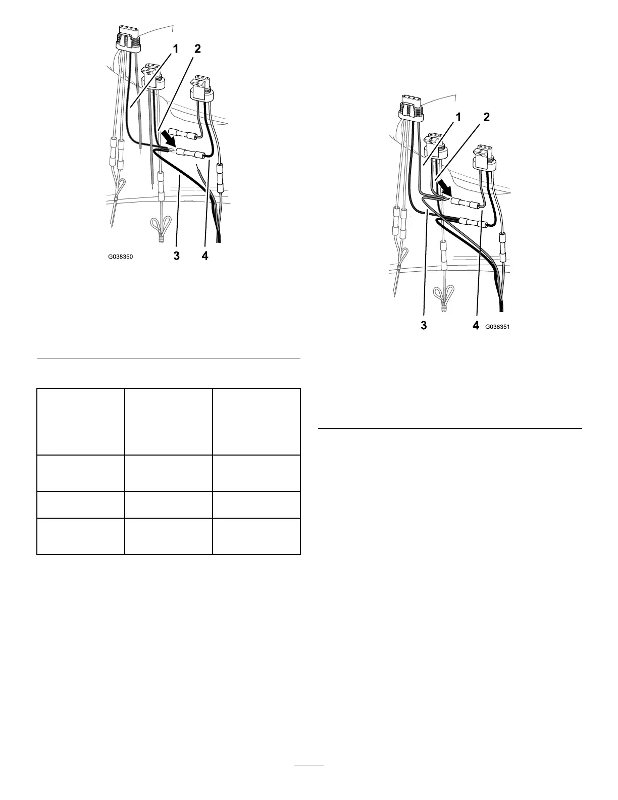
Figure46
1.Blackwire(4-pin
adapter—ratevalve)
3.Bluewire(DINwire
harness—master-spray
valve_
2.Blackwire(3-pin
adapter—agitationvalve)
4.Blackwire(3-pin
adapter—master-spray
valve)
WiringTable—Master-SprayValve
Wirecolor
codes—DINwire
harnesses
Wirecolor
codes—4-pin
adapterforthe
ratevalveand
3-pinadapterfor
theagitationvalve
Wirecolor
codes—3-pin
adapter
(master-spray
valve)
Brown
(master-spray
valve)
PinkPink
Blue(master-spray
valve)
BlackBlack
Yellow/green
(master-spray
valve)
NotapplicableWhite
4.Inserttheblackwireofthe4-pinadapterfortherate
valve,blackwireofthe3-pinadapteroftheagitation
valve,andbluewiresfortheDINwireharnessintothe
butt-spliceconnectorontheblackwireofthe3-pin
adapterforthemaster-sprayvalve.
5.Centerthecrimpingtooloverthebutt-spliceconnector
andwiresandcrimptheconnectorsecurely.
6.Alignthepinkwireofthe4-pinadapterfortherate
valveandthepinkwireofthe3-pinadapterofthe
agitationvalve,andthebrownwireoftheDINwire
harnesswiththepinkwireofthe3-pinadapterfor
themaster-sprayvalve;refertothewiretableforthe
master-sprayvalve.
7.Insertthepinkwireofthe4-pinadapterfortherate
valve,pinkwireofthe3-pinadapteroftheagitation
valve,andbrownwiresfortheDINwireharnessinto
thebutt-spliceconnectoronthepinkwireofthe3-pin
adapterforthemaster-sprayvalve.
Figure47
1.Pinkwire(4-pin
adapter—ratevalve)
3.Brownwire(DINwire
harness—masterspray
valve_
2.Pinkwire(3-pin
adapter—agitationvalve)
4.Pinkwire(3-pin
adapter—masterspray
valve)
8.Centerthecrimpingtooloverthebutt-spliceconnector
andwiresandcrimptheconnectorsecurely.
9.Useaheatguntoshrinktheinsulatingsleevesofthe
3butt-spliceconnectors.
23

 Loading...


