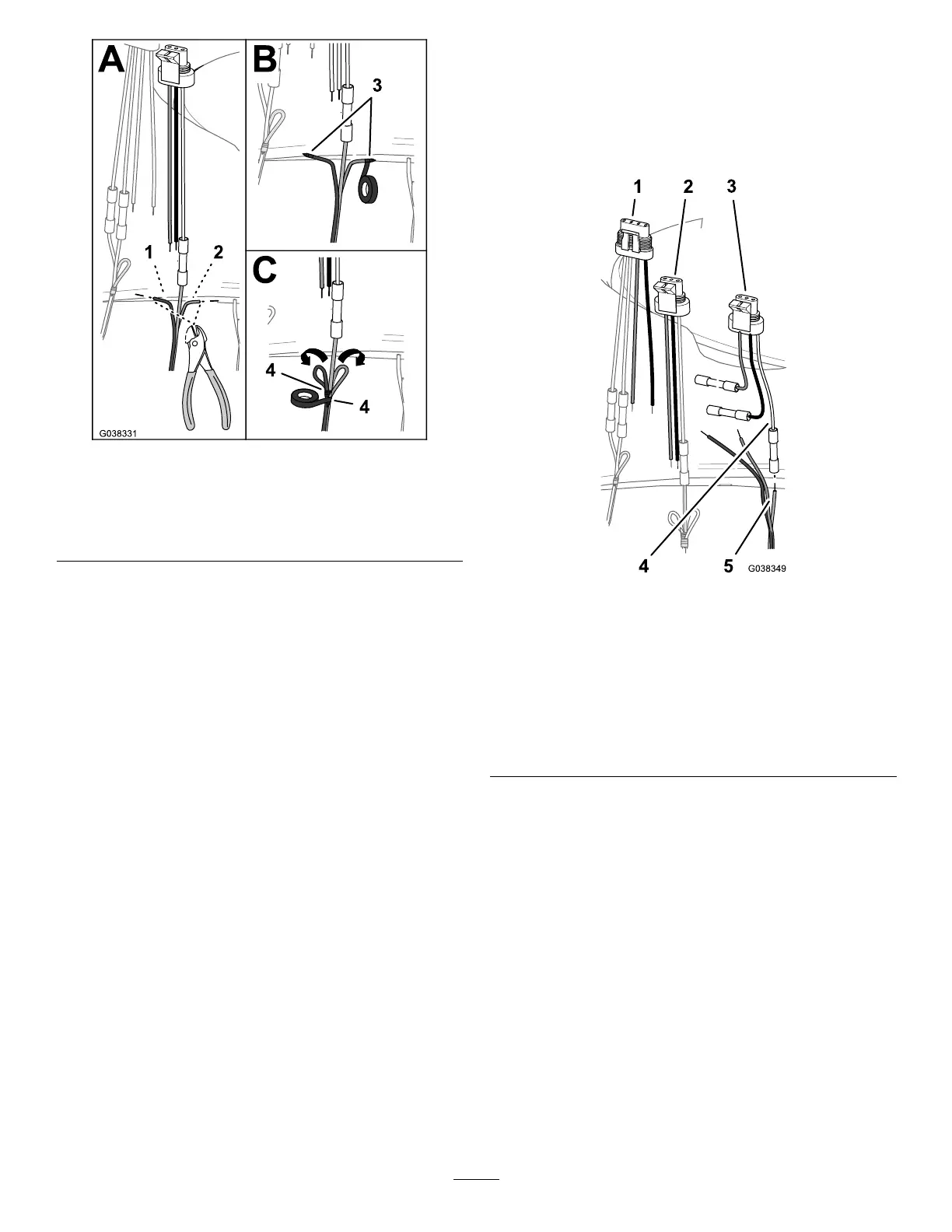
Figure44
1.Brownwire(cuttingthe
conductor)
3.Tapingtheendofthe
brownwireandbluewire
2.Bluewire(cuttingthe
conductor)
4.Tapingwirestogether
B.Wraptheendofthebrownwirewithelectrical
tapetosealthewire(Figure44).
C.Wraptheendofthebluewirewithelectricaltape
tosealthewire(Figure44).
D.Foldthebrownwireandbluewiretotheyellow
andgreenwireandwrapthe3wirestogetherwith
theelectricaltape(Figure44).
InstallingtheMaster-SprayValve
Connector
1.InserttheyellowandgreenwireoftheDINwire
harnessintothebutt-spliceconnectoronthewhite
wireofthe3-pinadapterforthemaster-sprayvalve
(Figure45).
Figure45
1.4-pinadapter(ratevalve)4.Whitewire(3-pin
adapter—master-spray
valve)
2.3-pinadapter(agitation
valve)
5.Yellowandgreen
wire(DINwire
harness—master-spray
valve)
3.3-pinadapter
(master-sprayvalve)
2.Centerthecrimpingtooloverthebutt-spliceconnector
andwiresandcrimptheconnectorsecurely.
3.Aligntheblackwireofthe4-pinadapterfortherate
valveandtheblackwireofthe3-pinadapterofthe
agitationvalve,andthebluewireoftheDINwire
harnesswiththeblackwireofthe3-pinadapterfor
themaster-sprayvalve;refertothewiretableforthe
master-sprayvalve(Figure46).
22