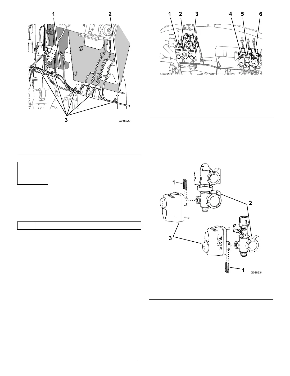
Figure50
1.Bracket(agitation,rate,
andmaster-sprayvalves)
3.Push-infasteners
2.Bracket(sectionvalves)
10
InstallingtheFlowMeterand
Hoses
Partsneededforthisprocedure:
1
Flow-meterhose—25x289mm(1x11-3/8inches)
RemovingtheValveActuators
Note:Performthisprocedureifyouneedadditional
clearancewheninstallingthehoseassembliesatthebottom
quick-connectportofthemanifoldvalve(s).
1.Withpiecesofmaskingtape,namethepositionofthe
valveactuator(s)asshowninFigure51.
Figure51
1.Ratevalveactuator
4.Leftspray-valveactuator
2.Agitationvalveactuator
5.Centerspray-valve
actuator
3.Masterspray-valve
actuator
6.Leftspray-valveactuator
2.Removetheretainerthatsecuresthevalveactuatorto
themanifoldvalveandseparatetheactuatorfromthe
valve(Figure52).
Note:Retainthevalveactuatorandretainerfor
installationinAssemblingtheValveActuatortothe
ManifoldValve(page27).
Figure52
1.Retainer3.Valveactuator
2.Manifoldvalve
25

 Loading...


