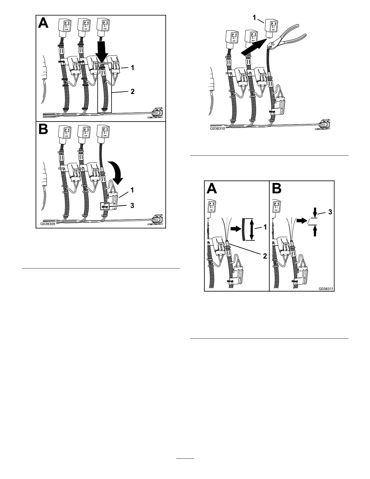
Figure31
1.Inline-fuseblock3.Cabletie
2.Positionedconvoluted
tubing
4.Aligntheinline-fuseblocktotheconvolutedtubingas
showninFigure31andsecurethefuseblocktothe
tubingwithacabletie.
5.CuttheDINconnectorharnessbelowtheDIN
connector(Figure32)
Note:Cuttheharnessasclosetotheconnector.
Figure32
1.DINconnector
6.Removea70mm(2-3/4inches)sectionofthe
sheathingfromtheDINconnectorharness(Figure33).
Figure33
1.Cablesheathing70mm
(2-3/4inches)
3.Removedsectionofwire
insulation—8mm(5/16
inch)
2.Wiresplice(factorymade)
7.Remove8mm(5/16inch)ofinsulationfromthe3
wiresoftheDINconnectorharness(Figure33).
8.Repeatsteps1though7forthewireharnessbranches
labelsCENTERSPRAYVALVE,LEFTSPRAYVALVE,RATE
VALVE,AGITATIONVALVE,andMASTERSPRAYVALVE.
InstallingtheRightSpray-Valve
Connector
1.AlignthewireinsulationcolorsoftheDINharness
tothewireinsulationcolorsofthe3-pinadapterfor
therightsprayvalveasshowninthewiretableforthe
rightsprayvalve.
17

 Loading...


