Figure77
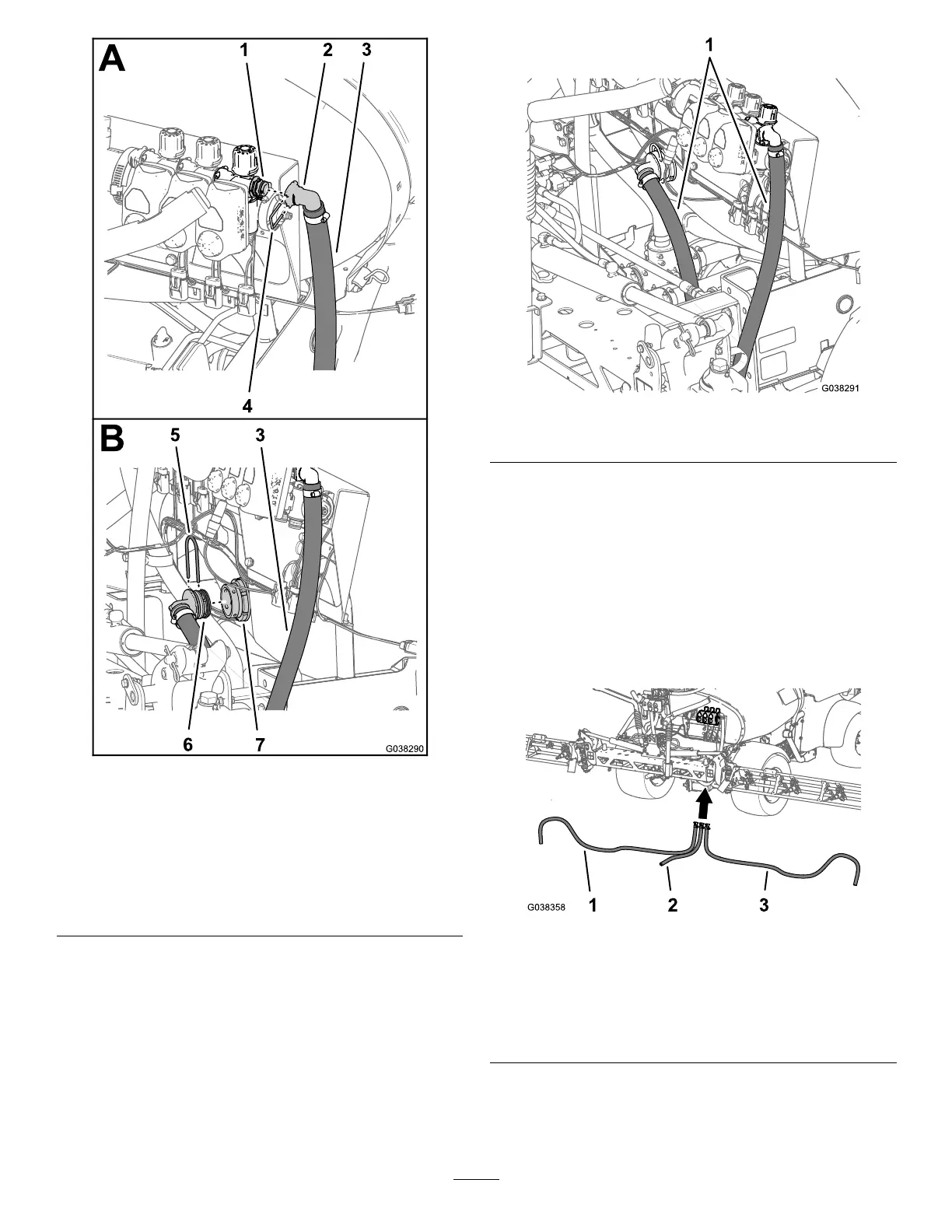
1.Quick-connecttting
(bypassmanifold)
5.Retainer(large)
2.90°quick-connecttting6.90°barbedtting
3.Sectionbypasshose—2.5
x146cm(1x57-1/2
inches)
7.Bulkheadtting(sprayer
tank)
4.Retainer(small)
2.Routethesectionbypasshosearoundtherightframe
channeltowardthebulkheadttinginthesprayertank
asshowninFigure78.
Figure78
1.Sectionbypasshose—2.5x146cm(1x57-1/2inches)
3.Assemblethe90°barbedttingofthesectionbypass
hoseintothebulkheadtting(Figure77).
4.Securethe90°ttingtothebulkheadtting(Figure77)
withtheretainer(large)thatyouremovedinstep1of
RemovingtheSectionBypassHose(page16).
InstallingtheSectionSupplyHoses
1.Routetheleft,center,andrightboom-supplyhosesto
theboom-sectionvalvesasshowninFigure79.
Figure79
1.Leftboom-supplyhose—2
x213cm(3/4x83-7/8
inches)
3.Rightboom-supply
hose—2x142cm(3/4x
55-7/8inches)
2.Centerboom-supply
hose—2x67cm(3/4x
26-5/16inches)
2.Assemblethestraightbarbedttingofthesupplyhose
fortheleftboom-supplyhoseontothequick-connect
ttingattheleft-boom-sectionvalve(Figure80).
38

 Loading...


