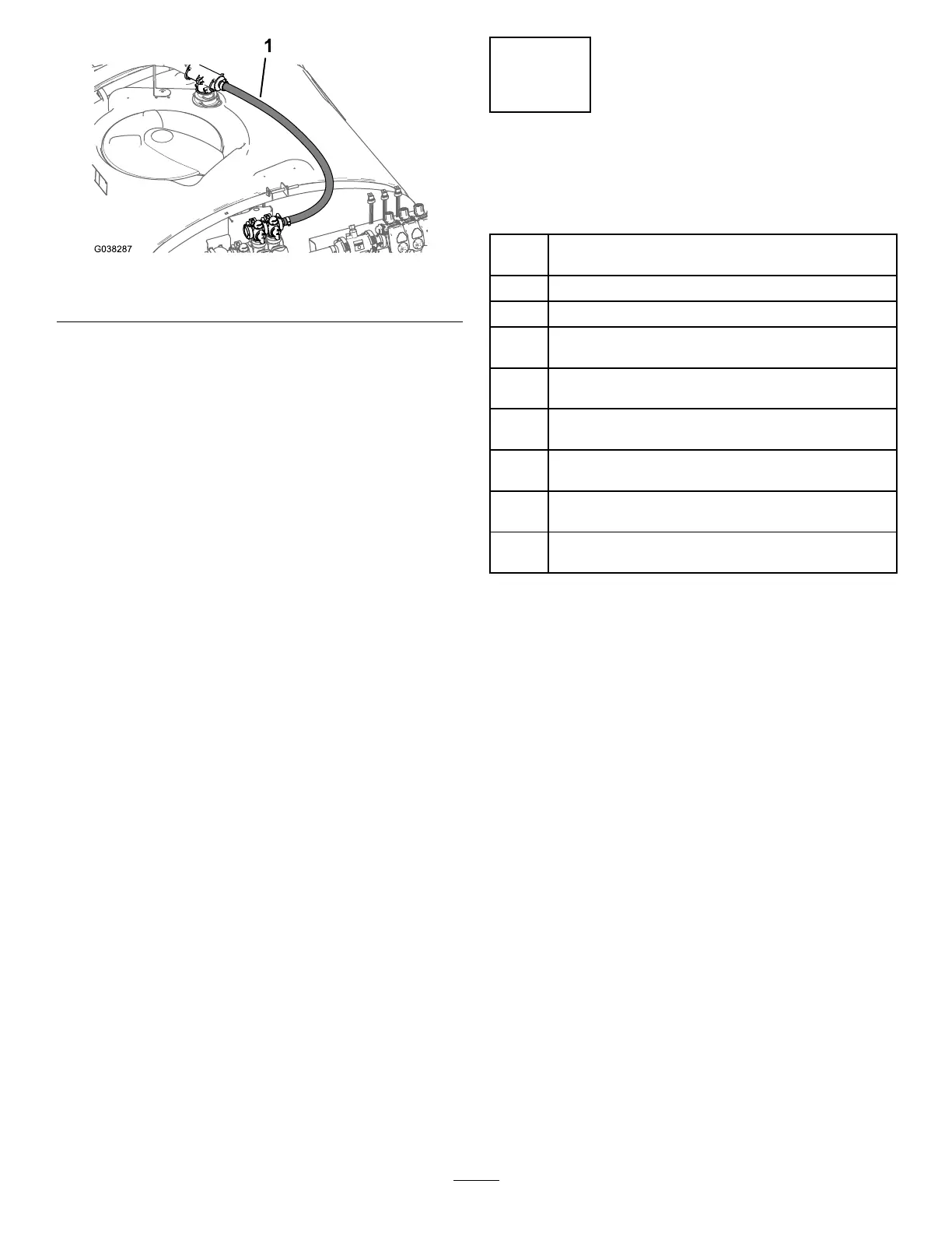
Figure69
1.Bypasshose—2.5x110cm(1x43-1/2inches)
4.Aligntheangeofthestraightbarbedttingand
gasket—25x35mm(1x1-3/8inches)withtheange
ofthebypassvalve(Figure68).
5.Securethestraightbarbedttingtothebypassvalve
(Figure69)withaangeclamp—40to64mm(1-9/16
to2-1/2inches).
15
InstallingtheSprayerSupply
Hose
Partsneededforthisprocedure:
1
Sprayersupplyhose—2.5x73cm(1x28-7/8
inches)—machineswithouttheoptionaleductorkit
2
Flangeclamp—40to64mm(1-9/16to2-1/2inches)
2
Gasket—25x35mm(1x1-3/8inches)
1
Supportclamp—machineswithouttheoptional
eductorkit
1
Flange-headbolt(5/16x3/4inch)—machineswithout
theoptionaleductorkit
1
Flangelocknut(5/16inch)—machineswithoutthe
optionaleductorkit
1
Lowersupplyhose—25x66cm(1x25-3/4inches)
machineswiththeoptionaleductorkit
1
Retainer(small)—machineswiththeoptionaleductor
kit
1
Uppersupplyhose—25x22cm(1x8-5/8inches)
machineswiththeoptionaleductorkit
InstallingtheSprayerSupply
Hose—MachinewithouttheOptional
EductorKit
Ifyourmachinehastheoptionaleductorkit,skiptoInstalling
theLowerSprayerSupplyHose—MachineswiththeOptional
EductorKit(page36).
1.Alignthe90°angedelbowofthesprayersupply
hose—2.5x73cm(1x28-7/8inches)witha
gasket—25x35mm(1x1-3/8inches)totheangeof
thelterhead(Figure70).
34