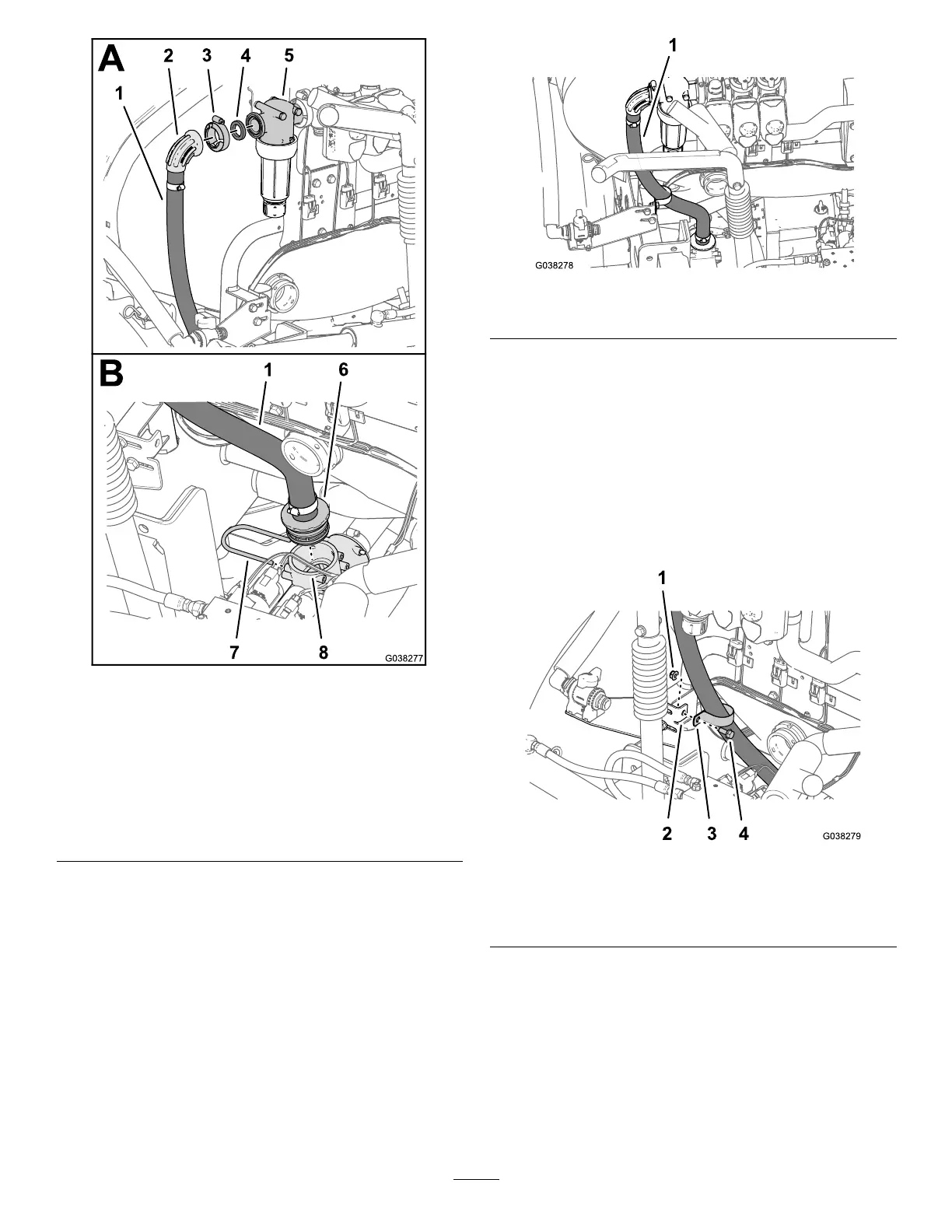
Figure70
1.Sprayersupplyhose—2.5
x73cm(1x28-7/8inches)
5.Filterhead
2.90°angedelbow6.Straightbarbedtting
3.Flangeclamp—40to
64mm(1-9/16to2-1/2
inches)
7.Retainer
4.Gasket—25x35mm(1x
1-3/8inches)
8.T-tting(forward,left
position)
2.Looselyassemblethesprayersupplyhoseandgasket
tothelterhead(Figure70)withaangeclamp—40
to64mm(1-9/16to2-1/2inches).
3.Routethesprayersupplyhosedownandtowardthe
T-ttinglocatedforwardofthepressure-reliefvalveas
showninFigure71.
Figure71
1.Sprayersupplyhose—2.5x73cm(1x28-7/8inches)
4.Assemblethestraightbarbedttingofthesprayer
supplyhoseintotheforward,leftT-tting(Figure70).
5.SecurethebarbedttingtotheT-ttingwiththe
retainerthatyouremovedinstep3ofDisconnecting
theReturn,Sprayer-Supply,andBypassHoses(page
14).
6.Securethehosetothesprayersupplyhosetothetab
oftheagitation-valvebracket(Figure72)withthe
ange-headbolt(5/16x3/4inch)andangelocknut
(5/16inch).
Figure72
1.Flangelocknut(5/16inch)3.Supportclamp
2.Agitation-valvebracket
4.Flange-headbolt(5/16x
3/4inch)
7.Tightentheangeclampthatsecuresthe90°anged
elbowofthesprayersupplyhosetothelterhead
(Figure70).
35