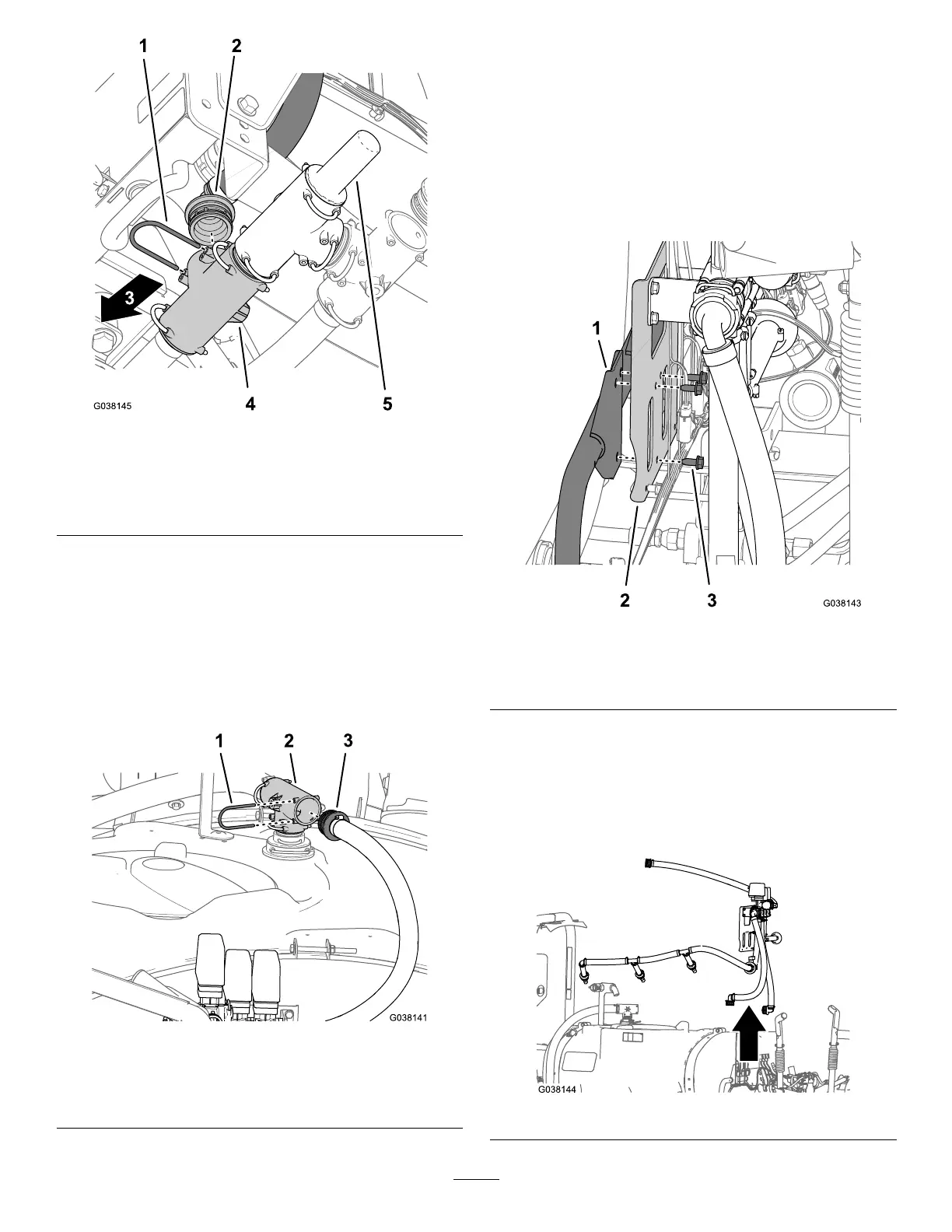
Figure24
1.Retainer
4.T-tting
2.90°barbedtting(sprayer
supplyhose)
5.Pressure-reliefvalve
3.Frontofthemachine
4.Removethe90°barbedttingfromtheT-tting
(Figure24).
5.Atthetopoftheofthesprayertank,removethe
retainerthatsecuresthestraightbarbedttingofthe
bypasshosetotheT-tting(Figure25).
Note:RetaintheretainersforinstallationinInstalling
theBypassHose—MachineswithouttheOptional
SprayWandKitorElectricHoseReelKit(page33).
Figure25
1.Retainer
3.Straightbarbedtting
(bypasshose)
2.T-tting
6.RemovethestraightbarbedttingfromtheT-tting
(Figure25).
RemovingtheAgitation,Rate,and
Master-SprayValvesfromtheMachine
1.Whilesupportingthebracketfortheagitation,rate,
andmaster-sprayvalves,removethe3ange-head
bolts(5/16x3/4inch)thatsecurevalvebrackettothe
mount(Figure26).
Figure26
1.Mount
3.Flange-headbolts(5/16x
3/4inch)
2.Bracket
2.Removethebracket,valves,hoses,andagitation
nozzlesfromthemachine(Figure27).
Note:Retainthe3ange-headbolts(5/16x3/4inch)
forinstallationinInstallingtheAgitation,Rate,and
Master-SprayValveManifold(page24);younolonger
needthebracket,valves,hoses,andagitationnozzles.
Figure27
15

 Loading...


