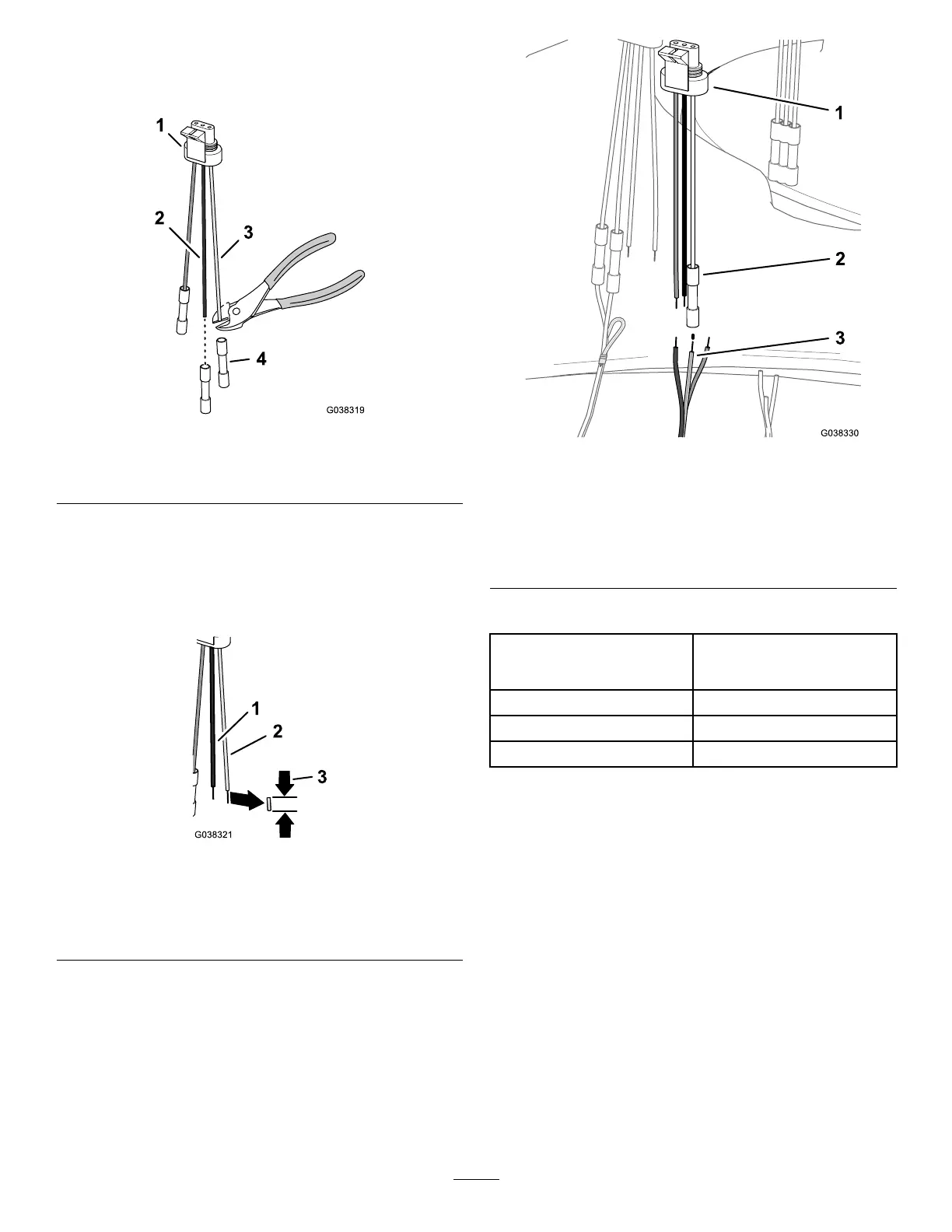
InstallingtheAgitationValveConnector
1.Cutoffthebutt-spliceconnectorsforthepinkwire
andblackwireofthe3-pinadapter(Figure41).
Figure41
1.3-pinadapter3.Pinkwire
2.Blackwire4.Butt-spliceconnector
2.Strip8mm(5/16inch)ofinsulationfromthepinkand
blackwiresofthe3-pinadapter(Figure42).
Note:Youwillconnectthepinkandblackwiresof
the3-pinadapterinInstallingtheMaster-SprayValve
Connector(page22).
Figure42
1.Blackwire(3-pinadapter)3.Removedsectionofwire
insulation—8mm(5/16
inch)
2.Pinkwire(3-pinadapter)
3.AligntheyellowandgreenwireoftheDINharness
withthewhitewireofthe3-pinadapterforthe
agitation-valve(Figure43);refertothewiretablefor
theagitationvalve.
Figure43
1.3-pinadapter3.Yellowandgreenwire
(DINharness—agitation
valve)
2.Butt-spliceconnector
(whitewire—agitation
valve)
WiringTable—AgitationValve
Wirecolorcodes—DINwire
harness
Wirecolorcodes—3-pin
adapter(agitation-valve
position)
NotapplicablePink
NotapplicableBlack
Yellow/green
White
4.InsertthewireoftheDINwireharnessintothe
butt-spliceconnectorofthe3-pinadapter.
5.Centerthecrimpingtooloverthebutt-spliceconnector
andwiresandcrimptheconnectorsecurely.
6.Useaheatguntoshrinktheinsulatingsleeveofthe
butt-spliceconnectorofthewiresthatyouinstalled
insteps3through5.
7.TerminatethebrownandbluewireoftheDIN
connectorasfollows:
A.Cuttheconductorsofthebrownwireandblue
wireushwiththeinsulation(Figure44).
21

 Loading...


