Multi Pro 1750
Page 5 − 22
Electrical System
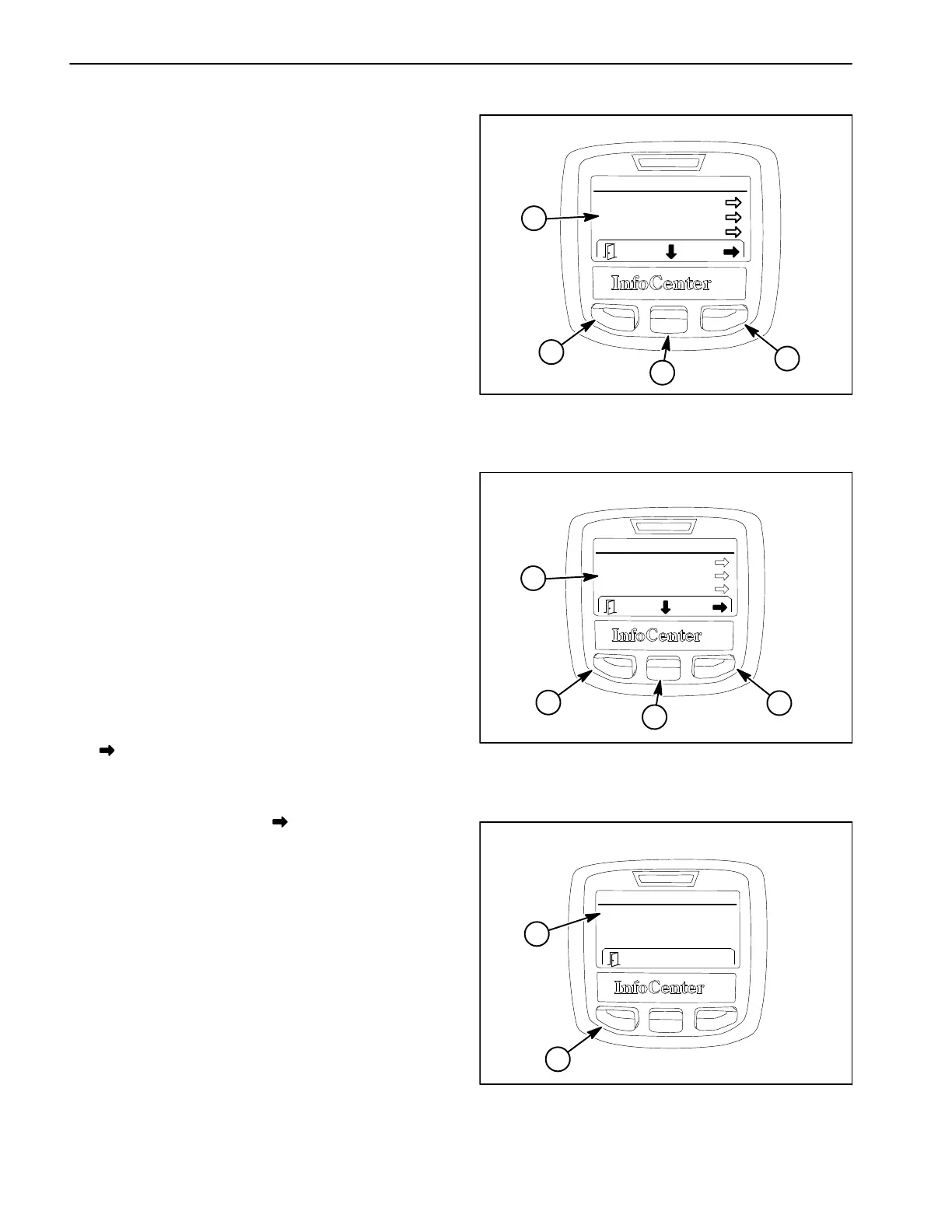
Using the InfoCenter Display for Troubleshooting
The diagnostics screen of the InfoCenter display can be
very helpful when troubleshooting machine operation is-
sues (see Diagnostics Screen in this chapter). The diag-
nostics screen (Fig. 23) lists a variety of machine
operations and the current state of the inputs, the quali-
fiers and the outputs required to allow the operation to
proceed. The electrical components involved in the fol-
lowing machine operations can be evaluated using the
diagnostics screen prior to testing each component indi-
vidually:
Pumps The components necessary to operate the
spray pump and the optional rinse pump.
Booms The components necessary to operate the
master boom spray valve.
Engine The components necessary to start and run
the engine.
Throttle Lock The components necessary to en-
gage the throttle lock/speed lock.
If a machine operation is malfunctioning, the following
procedure can help identify the cause of the component
or circuit wiring causing the malfunction.
1. Park machine on a level surface, engage parking
brake and stop engine.
2. Set the ignition switch to the ON position and navi-
gate to the InfoCenter Diagnostic Screen.
3. Select (highlight) the malfunctioning machine opera-
tion and press the Right/forward button (as indicated by
the
at the bottom of the screen). For this example,
the Pumps operation has been selected (Fig. 24).
4. Select (highlight) Inputs and press the Right/forward
button (as indicated by the
at the bottom of the
screen).
5. Manually operate each input item listed (Fig. 25).
The input condition on the InfoCenter display should al-
ternate ON and OFF as the input is switched open and
closed. If ON and OFF do not alternate during input op-
eration, the input component or its circuit wiring is faulty
and should be tested (see Component Testing in this
chapter).
In the Pumps operation example, the only input is the
Spray Pump Switch (unless the machine has an option-
al rinse pump kit). If ON and OFF do not alternate when
the switch is toggled ON and OFF, the switch or the cir-
cuit wiring for the switch is faulty and should be tested
as described.
Figure 23
1. Diagnostics items
2. Left/back button
3. Center/down button
4. Right/forward button
DIAGNOSTICS SCREEN
Diagnostics
Pumps
Booms
Engine Run
1
2
3
4
Figure 24
1. Diagnostics items
2. Left/back button
3. Center/back button
4. Right/forward button
Pumps
Inputs
Qualifiers
Outputs
1
DIAGNOSTICS SCREEN (PUMPS SELECTED)
2
3
4
Figure 25
1. Input items 2. Left/back button
Pumps
Pump Switch:
1
DIAGNOSTICS SCREEN (PUMPS INPUTS SELECTED
ON
2