Multi Pro 1750 ChassisPage 8 − 17
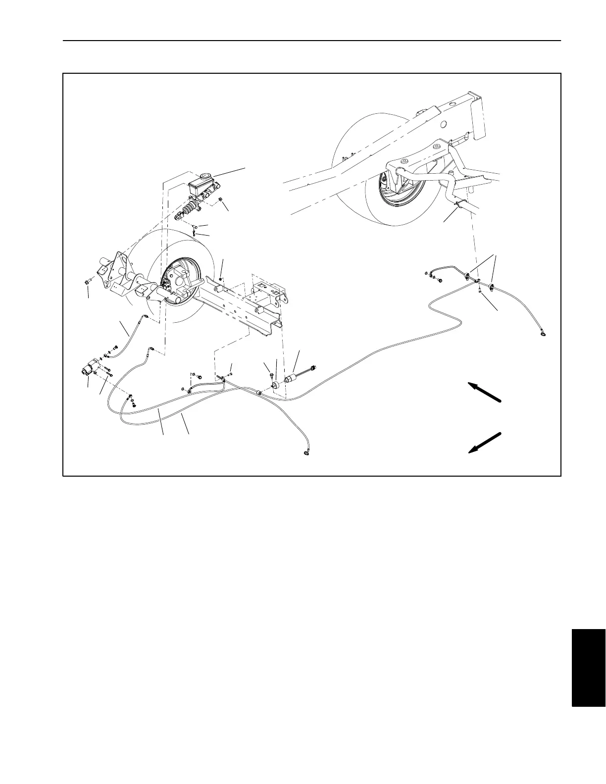
Brake Lines
1. Brake line − rear
2. Brake line − front
3. Brake line − rear
4. Cap screw (2)
5. Flange head screw
6. R−Clamp
7. Pressure switch
8. Tie clip (2)
9. Brake hold valve
10. Hex washer head (2)
11. Master cylinder
12. Flange nut (2)
13. Flange head screw (2)
14. Clevis pin
15. Hair pin
16. Lock nut
17. Cable tie
Figure 10
FRONT
RIGHT
11
12
13
14
15
16
17
1
2
3
4
4
5
6
7
8
9
10
When performing service work on the Multi Pro brake
lines, make sure to clean brake components before dis-
assembly. Record routing of brake lines and location of
cable ties and clamps before removing brake lines from
machine. Reinstall brake lines with all cable ties and
clamps as recorded. Make sure that the brake lines do
not contact moving components during machine opera-
tion.
Chassis