Multi Pro 1750
Page 5 − 44
Electrical System
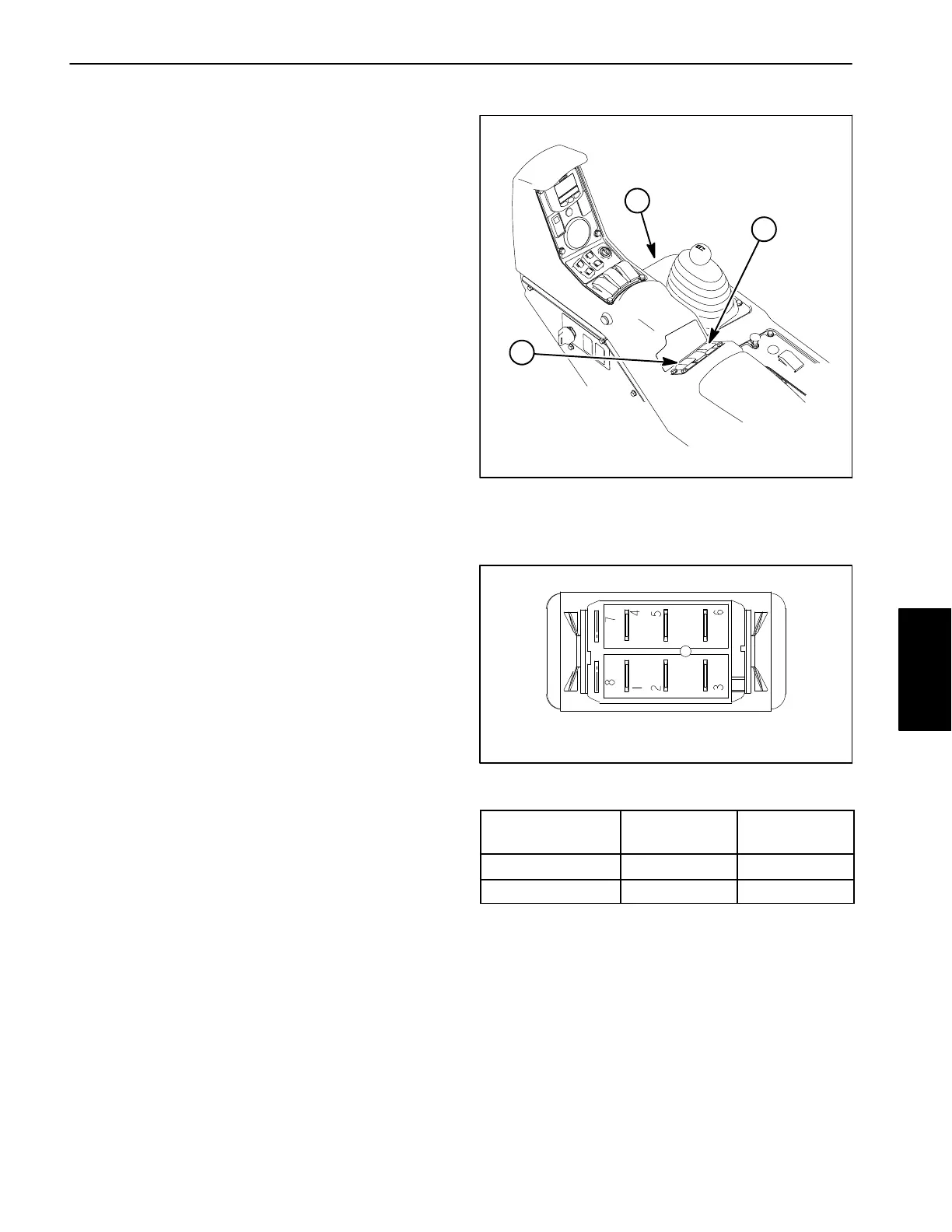
Spray Pump and Agitation Switches
The spray pump and agitation switches are identical
switches and are located on the control console
(Fig. 50). These switches include an indicator light to
notify the operator when the switches are in the ON posi-
tion.
The spray pump switch allows the operator to energize
or de−energize the spray pump electric clutch. The Toro
Electronic Controller (TEC) monitors the operation of
the spray pump switch as an input and provides an out-
put to energize the pump electric clutch when appropri-
ate.
NOTE: To avoid damaging the spray pump drive, the
spray pump switch will only engage when the engine is
at low idle and either the master boom (spray enable)
switch is disengaged or the master boom switch is en-
gaged but none of the boom spray switches are en-
gaged.
The agitation switch allows the operator to energize or
de−energize the spray system agitation valve for spray
tank agitation. On machines with a serial number below
315000000, the switch reverses the polarity of the volt-
age supplied to the agitation valve actuator (2 wire). On
machines with a serial number above 315000000, the
switch removes or applies voltage to the activator termi-
nal (C) to control the agitation valve actuator operation.
Testing
The spray pump switch and its circuit wiring can be
tested as a TEC input or qualifier using the InfoCenter
Display (see InfoCenter Display − Diagnostics Screen in
this chapter). If testing determines that the switch and
circuit wiring are not functioning correctly, proceed with
the following test procedure:
1. Park machine on a level surface, stop spray pump,
stop engine and engage parking brake. Remove key
from ignition switch.
2. Remove console panel. Locate switch that is to be
tested and unplug machine wire harness connector
from switch.
3. With the use of a multimeter (ohms setting), the
switch functions may be tested to determine whether
continuity exists between the various terminals for each
switch position. The switch terminals are marked as
shown (Fig. 51) and the circuitry of the switch is shown
in the chart (Fig. 52). Verify continuity between switch
terminals.
4. Replace switch if testing determines that it is faulty.
1. Control console
2. Pump switch
3. Agitation switch
Figure 50
1
2
3
Figure 51
BACK OF SWITCH
SWITCH
POSITION
NORMAL
CIRCUITS
OTHER
CIRCUITS
OFF 2 + 1 5 + 4
ON 2 + 3 5 + 6
Figure 52
5. Switch terminals 7 (−) and 8 (+) are used for the indi-
cator light in the switch.
6. If the switch tests correctly and a circuit problem still
exists, check wire harness (see Electrical Schematic
and Wire Harness Drawings in Chapter 10 − Electrical
Drawings in this manual).
7. After testing is completed, connect the harness con-
nector to the switch. Install console panel to machine.
Electrical
System