Multi Pro 1750Page 6 − 48Spray System
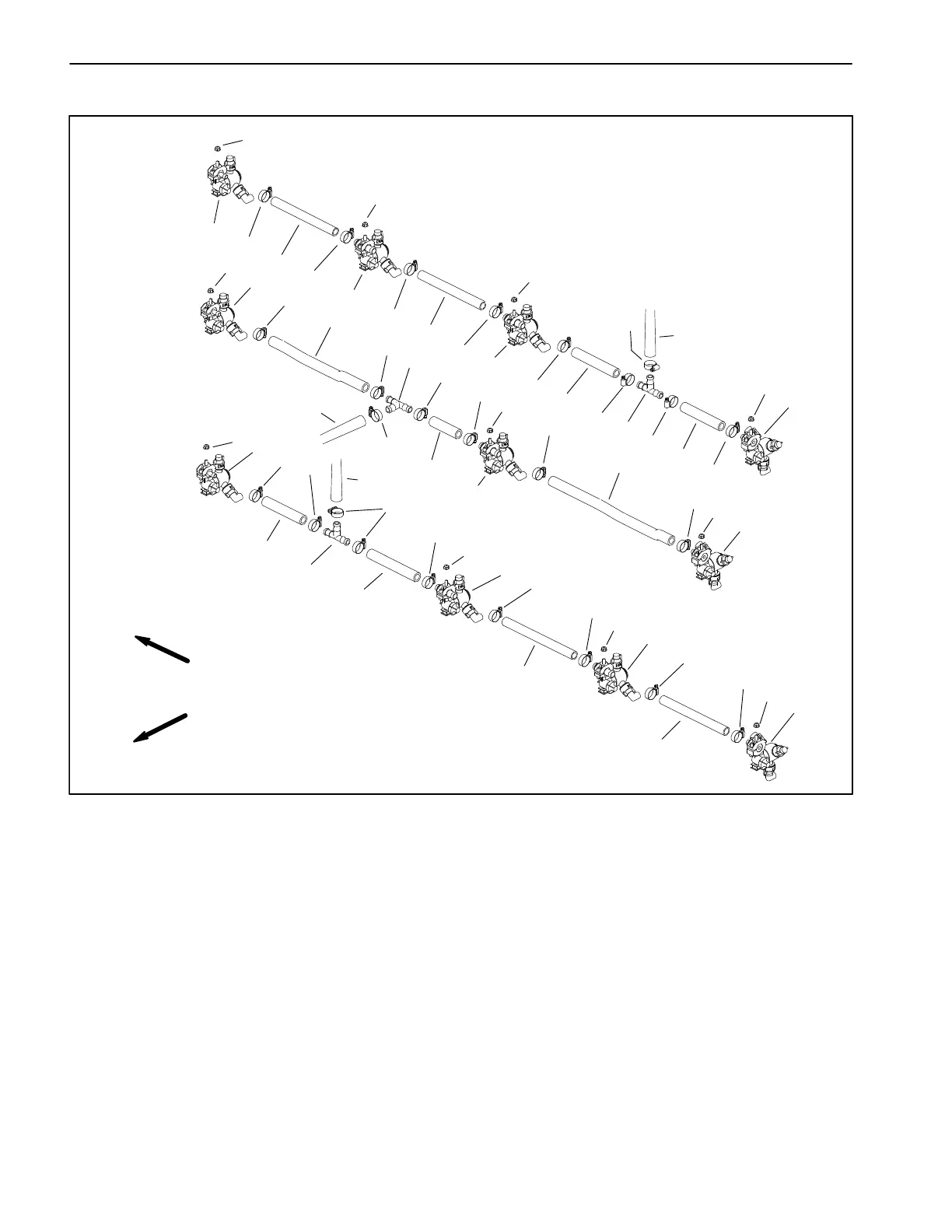
Turret Bodies
1. Flange nut (11)
2. Turret body − RH barb (3)
3. Turret body − LH barb (3)
4. Turret body − dual barb (5)
5. Tee fitting (3)
6. Hose clamp (25)
7. Hose 18.75” (47.6 cm) (4)
8. Hose 12.25” (31 cm) (2)
9. Hose 6” (15.2 cm) (2)
10. Hose 4.12” (10.5 cm)
11. Hose − formed RH
12. Hose − formed LH
13. Hose (from left boom spray valve)
14. Hose (from center boom spray valv
15. Hose (from right boom spray valve)
Figure 32
FRONT
RIGHT
RIGHT
BOOM
LEFT
BOOM
CENTER
BOOM
1
2
3
4
10
11
12
14
15
1
1
1
1
1
1
1
1
1
1
2
2
3
3
4
4
4
4
5
5
5
6
6
6
6
6
6
6
6
6
6
6
6
6
6
6
6
6
6
6
6
6
6
6
6
7
7
7
7
8
8
9
9
13
Removal (Fig. 32)
IMPORTANT: Make sure to remove and neutralize
chemicals from spray components before disas-
sembly. Wear protective clothing, chemical resist-
ant gloves and eye protection during repair.
1. Park machine on a level surface, stop spray pump,
stop engine and engage parking brake. Remove key
from ignition switch.
2. Loosen hose clamp(s) and remove supply hose(s)
from turret body.
3. Remove flange nut (item 1) that secures turret body
to mount bracket and remove turret body from machine.
Installation (Fig. 32)
NOTE: The position of the hose barb on the turret body
determines the turret body’s location on the spray boom.
1. Position turret body to mount bracket on spray boom
and secure it in place with flange nut (item 1).
2. Install supply hose(s) to turret body. Tighten hose
clamp(s).