Multi Pro 1750 Page 7 − 21 Drive Train
Transaxle Service
Transaxle Disassembly
1. Thoroughly clean outside surface of transaxle.
NOTE: Item numbers in figures are shown in order of
disassembly; for example, remove item 1 first, then item
2, etc. Assemble in reverse order; for example, install
item 1 last.
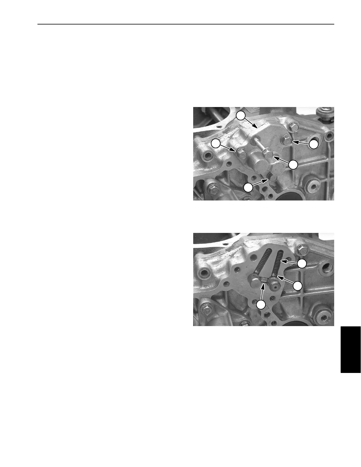
2. Loosen flange head screws and remove fork shaft
case from center plate. Note location of longer flange
head screw. Be careful when removing cover as steel
balls inside are spring loaded.
1
3
2
2
2
1. Flange head screw (1)
2. Flange head screw (3)
3. Fork shaft case
Figure 16
3. Hold your hand over the area and shift R−1 and 2−3
levers to move rails outward so balls, springs and
spindle can be removed.
4. Inspect fork shaft case for cracks or damage and re-
place if necessary.
1
2
3
1. Spindle
2. Spring (2)
3. Ball (2)
Figure 17
Drive Train