Multi Pro 1750 Page 6 − 35 Spray System
Control Valve Service (Serial Number Above 315000000)
The Multi Pro 1750 uses several valves in the spray sys-
tem. Each valve is fully serviceable. Use the following
procedure for servicing the rate, agitation, agitation by-
pass, master boom, master boom bypass, left spray
boom, center spray boom and right spray boom valves.
IMPORTANT: Make sure to remove and neutralize
chemicals from spray components before valve mo-
tor disassembly. Wear protective clothing, chemical
resistant gloves and eye protection during repair.
Disassembly (Fig. 21)
1. Locate the valve being serviced and remove either
the actuator fork and the actuator assembly or the screw
and knob from the valve.
2. Remove hoses, fittings, clamps and adapters as
necessary to access valve end caps.
3. Rotate the end caps counterclockwise (unscrew)
and remove the end caps.
4. Rotate the valve stem until the slot in the stem and
valve ball are in−line with the valve body and remove the
valve ball.
5. Remove the valve stem fork, seat, and remove the
valve stem assembly.
Assembly (Fig. 21)
1. Inspect the end cap and the stem seals and O−rings.
Replace components as necessary.
2. Apply silicone grease to seals and O−rings on stem
assembly. Install stem assembly, seat and fork.
3. Rotate the valve stem until the slot in the stem is in−
line with the valve body and install the valve ball.
4. Apply silicone grease to seals and O−rings on end
caps and install end caps. Tighten end caps until seated.
Do not over−tighten end caps.
5. Install hoses, fittings, clamps and adapters previous-
ly removed.
6. Install either the actuator and actuator fork or knob
and screw.
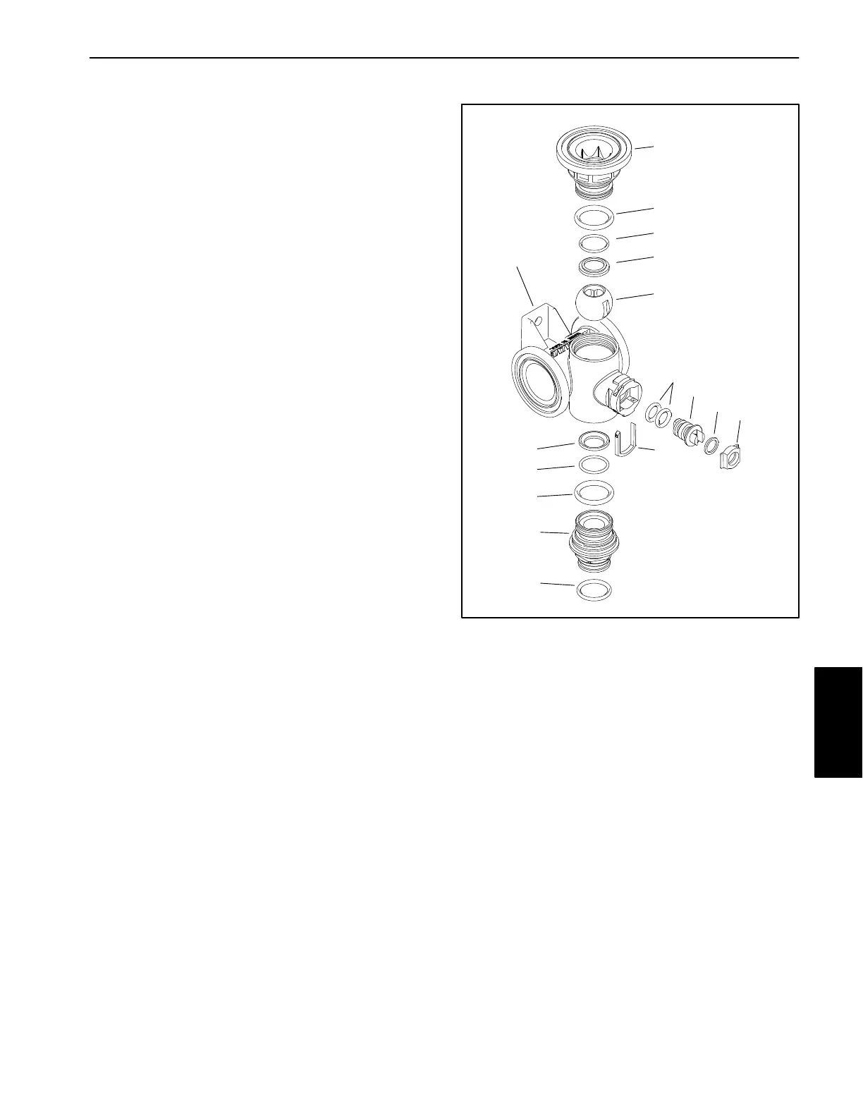
1. Valve body
2. End cap
3. Seat (2)
4. O−Ring (2)
5. O−Ring (2)
6. O−Ring
7. Ball
8. Stem fork
9. O−Ring (2)
10. Stem
11. Washer
12. Stem seat
Figure 21
Typical Spray Valve Assembly
1
2
3
4
5
6
7
8
9
10
11
2
3
4
5
12
Spray
System