Appendix A: Ordering Genuine Ithaca Supplies
100-11672 - Rev D Page 137
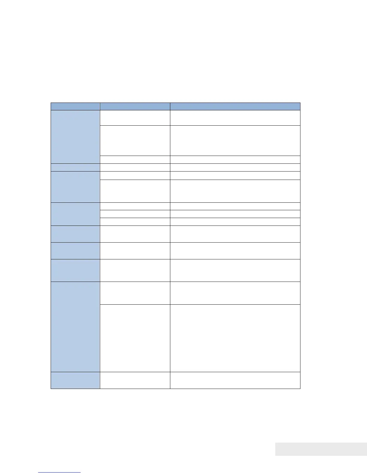
Adjustment
Adjustment When Replacing Parts
This section describes the works to be carried out, as an after-sale service,
after parts replacement.
Reference section in manual
"Work at Print Module Replacement"
Input of various
adjustment values
(*1) (Indicated on
labels)
"Print Module Replacement Procedure"
"Head Position Adjustment"
"Head Position Adjustment"
"Blade Position Adjustment"
Input of Purge Unit
wipe position
(Indicated on label)
"Consumable Parts Replacement
Procedure"
"Pinch Roller Position Adjustment"
"Head Position Adjustment"
"Backfeed Gap Adjustment"
"Work at Rack Unit Replacement"
Lift Unit / Rear
Feeder sensor
"Rear Feeder Sensor Adjustment"
Stacker Rail /
Front Tray
Unit
"Work at Stacker Rail and/or Front Tray
Unit Replacement"
In the case data can
be retrieved (Send
the data to Printer )
"• In the case data can be retrieved from
Printer Controller PCB to PC."
In the case data can
be retrieved (serial
number, time, various
adjustment values
(*1), Rear Feeder
Sensor, ink eject
power, Printhead
position, backfeed
gap)
"• In the case data cannot be retrieved
from Printer Controller PCB to PC."
"DC Power Supply Unit Replacement
Procedure"
(*1) Printhead wipe position, Printhead capping position, Printhead print
position, and Purge Unit wipe position
(*2) T-K gap, slant, and Head position
(*3) Use adjustment tool (supplied with service parts).