19
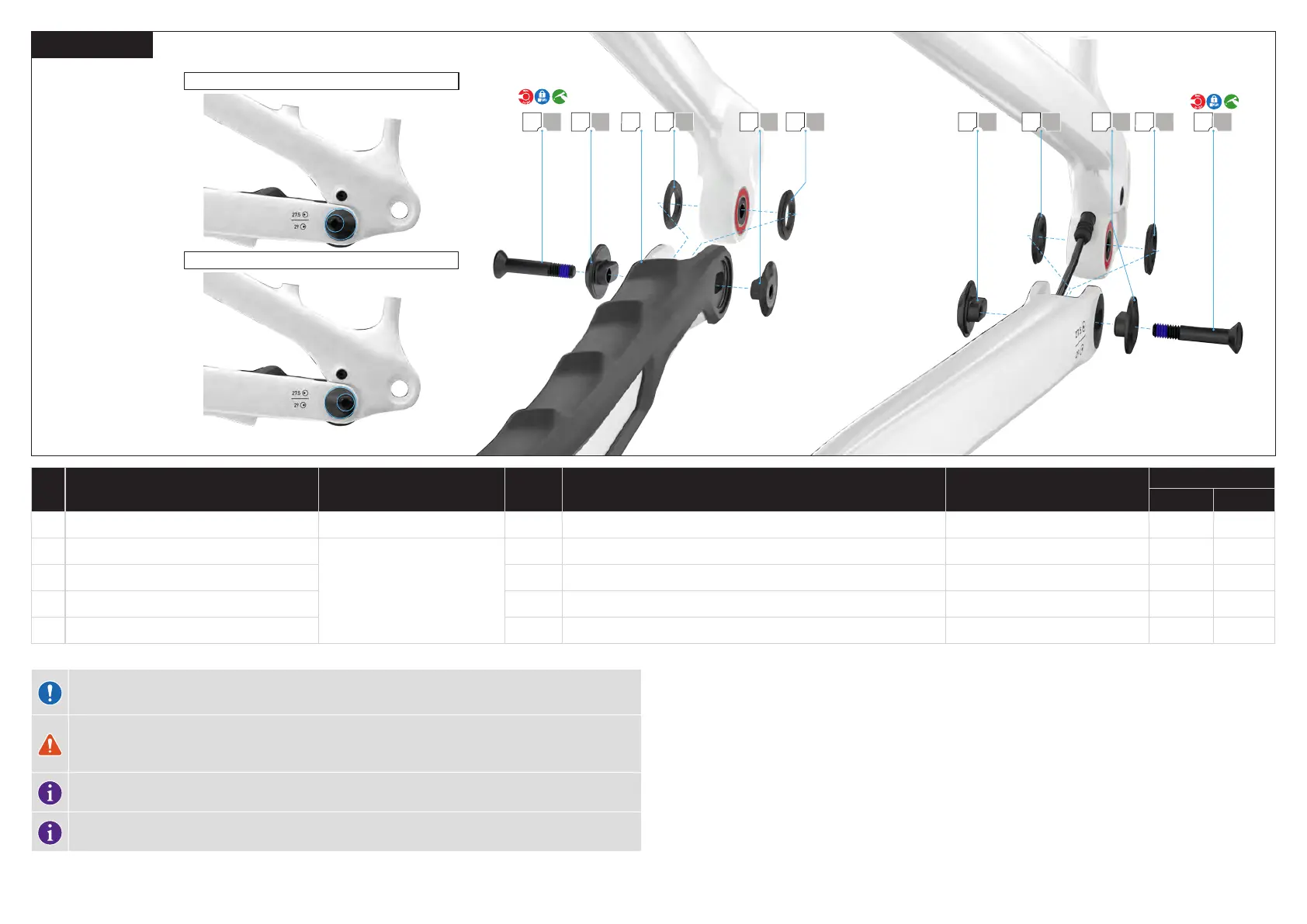
6.1.9. HORST PIVOT
FLIP CHIP - 27.5 “REAR WHEEL (DEFAULT)
FLIP CHIP - 29" REAR WHEEL
CAUTION: Before installing a 29"rear wheel on a S1 or S2 size frame, consult section 6. GENERAL NOTES
ABOUT ASSEMBLY in the Levo SL User Manual regarding saddle clearance.
WARNING: The drive side and non-drive side Horst flip chips must both be aligned in the same 27.5" or
29" position. Improperly installed flip chips can damage the frame and can also cause you to lose control
and fall.
Always assemble the chainstay protector before assembling the horst pivot flip chips and bolts
Once the flip chips are installed and torqued, there will be a small gap between the outer flange and the
chainstay. Do not over tighten
Clean the chainstay, then attach the chainstay protector (A) to the drive side chainstay with the protector over the
flip chip pivot hole.
# PART NAME SERVICE PART NUMBER QTY SPEC / DESCRIPTION TOOL
TORQUE
Nm in-lbf
A Chainstay protector
S216900005
1 CS PROTECTOR,MTB,PA TRAIL FSR G1.1 N/A N/A N/A
O Horst pivot bolt
S214200059
2 M6 x 32.5 mm 1 mm p, bolt 5 mm hex 10 90
P Horst link outer flip chip 2 DO PIVOT SPACER,GEO ADJ,6.0 ID, FLIP CHIP N/A N/A N/A
Q Horst link outer spacer 4 12 mm id x 21 mm od x 2.5 mm w, spacer N/A N/A N/A
S Horst link inner flip chip 4 DO PIVOT SPACER,GEO ADJ 6 MM X 1 MM, FLIP CHIP N/A N/A N/A
Grease the spacers (Q) (x4) and place the reduced surface side against the bearings (B).
Rotate and align the seatstay pivot with the chainstay pivot while pulling the excess speed sensor cable from the
motor area.
NOTE: Ensure the speed sensor cable is free from the Horst pivot and cannot get pinched which would damage
the cable.
Depending on the size of your rear wheel, align the flip chip inner (S) and outer spacers (P) in either the 27.5"or
29" position and place them against the frame.
Ensure that the inner and outer flip chip spacers are aligned in the same direction.
Make sure all flip chips are fully seated and aligned with the chainstay protector before inserting the bolt.
Grease all non-threaded surfaces and install the Horst link pivot bolts (O). Use a 5 mm hex key to hand tighten
only.