42
D
E
KICEJDBHAGF
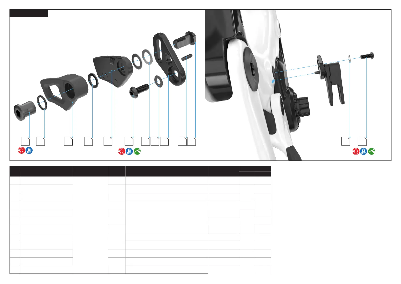
6.4.2. CHAIN GUIDE
Place the chain guide on the frame, then insert the chain guide pin
into the hole in the frame. This prevents the chain guide from rotating
when torquing.
Grease all the non-threaded surfaces of the chain guide mounting
bolt (D) and insert the bolt and washer (E) through the chain guide
back plate into the drive side center motor mounting bolt.
Use a torque wrench and T25 Torx bit to torque the bolt to
specification.
Rotate the outer chain guide to face upward.
# PART NAME
SERVICE PART
NUMBER
QTY SPEC / DESCRIPTION TOOL
TORQUE
Nm in-lbf
Chainguide (Carbon ver.2)
S231200005
1
CHG LEVO SL (GEN.2), CARBON FRM, CHAIN GUIDE,
MOTOR BOLT MOUNTED, 32-34T
N/A N/A N/A
A Chain guide outer plate 1 CHAIN GUIDE,OUTER PLATE N/A N/A N/A
B Chain guide inner plate 1 CHAIN GUIDE,INNER PLATE N/A N/A N/A
C Chain guide back plate 1 BACK PLATE,PA TRAIL FSR C1 N/A N/A N/A
D Chain guide mounting bolt 1 M5 x 14 mm, bolt T25 Torx 3.5 30
E Chain guide washer 1 5,1 mm id x 10 mm od x 0.9 mm thick, washer N/A N/A N/A
F Chain guide mounting nut 1 M8 x 1.0 mm p, nut 5 mm hex 4.5 40
G O—ring 1 9 mm id x 1.5 mm w, O-ring N/A N/A N/A
H Spacer outer 1 8.1 mm id x 15 mm od x 1 w, spacer N/A N/A N/A
I Back plate dowel pin 1 3 mm od x 10 mm l, dowel pin N/A N/A N/A
J Spacer inner 2 8.2 mm id x 13 mm od x 0.5 mm thick, washer N/A N/A N/A
K Mounting bolt 1 M8 x 1.0 mm p, slotted bolt N/A N/A N/A