34
6.3.7. MOTOR: STEP 3
# PART NAME SERVICE PART NUMBER QTY SPEC / DESCRIPTION TOOL
TORQUE
Nm in-lbf
Motor mounting hardware kit
S210500018
1 BLT MY22 LEVO SL CARBON MOTOR MOUNTING HARDWARE KIT N/A N/A N/A
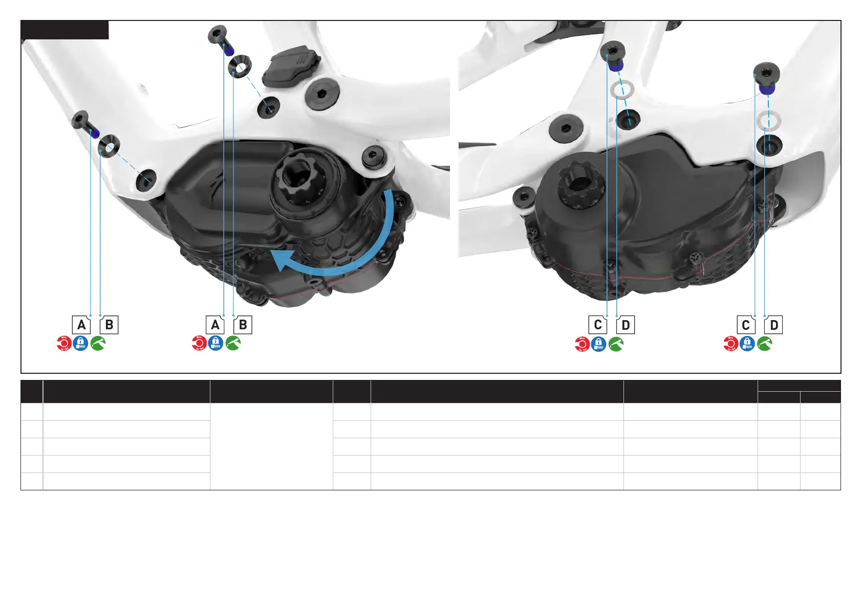
A NDS motor bolt 3 M6 x 20 mm x 1.0 mm p, bolt 5 mm hex 10 90
B NDS motor washer 3 6.4 mm id x 16 mm od x 4 mm thick, washer N/A N/A N/A
C DS motor bolt 3 M10 x 14 mm x 1.0 mm p, bolt 5 mm hex 13 115
D DS motor washer 3 11 mm id x 16 mm od x 0.5 mm thick, washer N/A N/A N/A
Rotate the motor assembly into the frame. Make sure the motor bolt holes are aligned with the frame bolt holes.
Grease the non-threaded surfaces and insert the remaining non-drive side motor mounting bolts (A) and washers
(B) into the frame using a 5 mm hex key.
Grease the non-threaded surfaces and insert the remaining drive side motor mounting bolts (C) and washers (D)
using a 5 mm hex key.
Torque all drive side motor bolts to specification.
Torque all non-drive side motor bolts to specification.