43
C
BA
D E
1
2
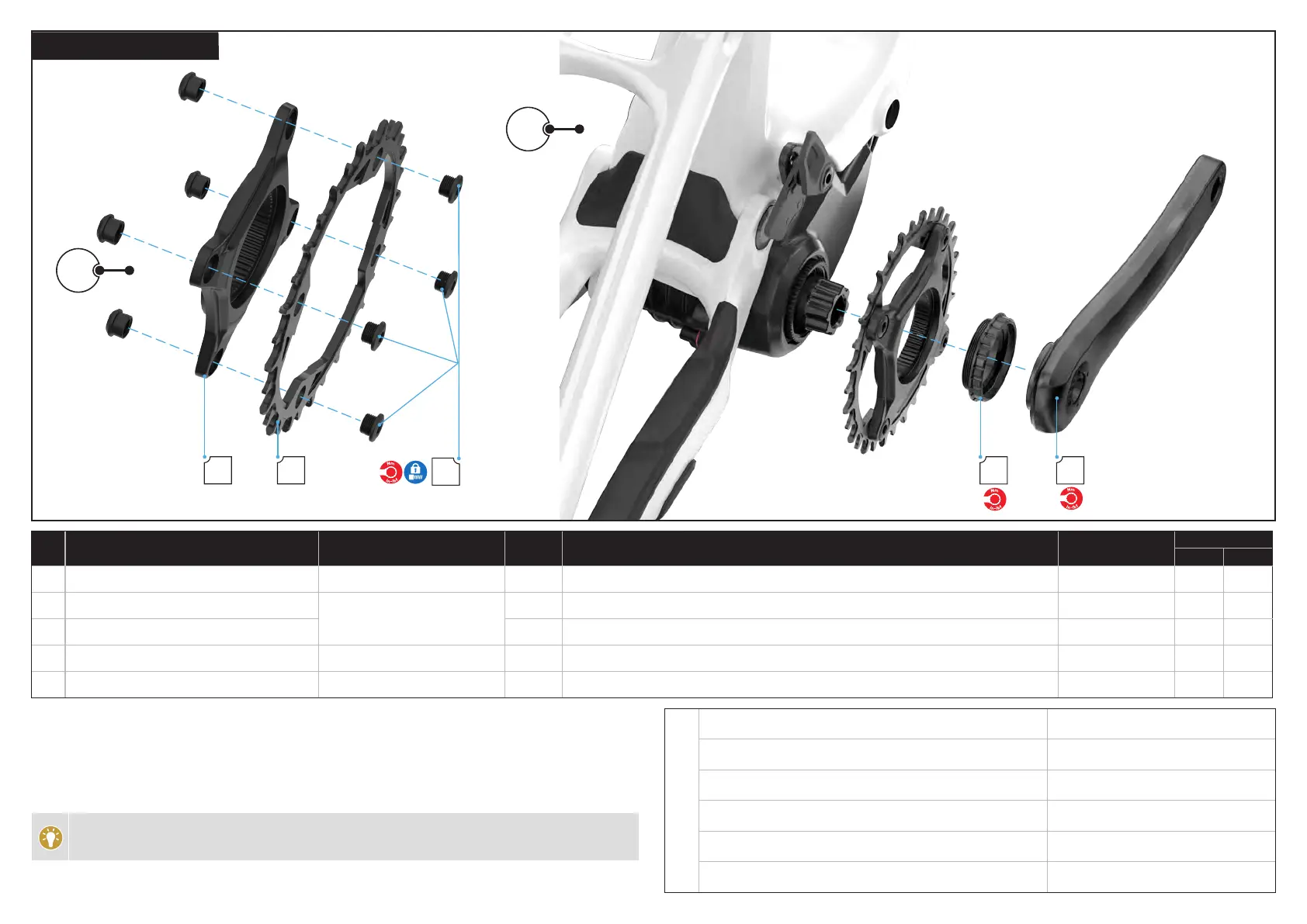
6.4.3. SPIDER AND CHAINRING
# PART NAME SERVICE PART NUMBER QTY SPEC / DESCRIPTION TOOL
TORQUE
Nm in-lbf
A Spider
S215100003
1 SPR TURBO, SL SYSTEM, M20 MOTOR SPIDER, 104 BCD, 4-BOLT, ALLOY, SRAM (00.6218.030.003)
N/A N/A N/A
B Chain ring
S211400008
1 CHR SRAM CHAINRING EAGLE 32T 104BCD ALLOY EMTB W/BOLTS (00.6218.040.000)
N/A N/A N/A
C Chain ring bolts 4 M8.5 X 5 mm x 1 mm p, bolt 5 mm hex 10 90
D Spider lock ring
S225100001
1 SPR SUB, TURBO, SL SYSTEM, SL M20 MOTOR, SPIDER LOCK RING Park Tool BBT-79 49 434
E Crank arms
SEE TABLE
1 CRK TURBO, SL M20, MOUNTAIN, 165 MM - 175 MM, L+R ARMS, CARBON / ALLOY, SRAM 8 mm hex 54 478
1. Assemble the chainring to the spider with the four chainring bolts and nuts. Use a torque wrench and a 5 mm
hex bit to torque the bolts to specification.
2. Grease the center spindle of the spider and slide the spider and chainring over the drive side motor spindle.
Insert the spider locking bolt and thread it onto the motor spindle. Install the chain: Determine the custom chain
length according to the manufacturer’s guidelines. Using a lock ring tool, tighten the lock ring nut to specification.
Assemble both crank arms. Use a torque wrench and a 8 mm hex bit to torque the bolt to specification.
Assemble the chain and rear wheel. Hold the rear wheel to prevent the chainring from rotating while
tightening the lock ring.
E
Crank arms Carbon 165 mm
S211600039
Crank arms Carbon 170 mm
S211600040
Crank arms Carbon 175 mm
S211600041
Crank arms Alloy 165 mm
S211600036
Crank arms Alloy 170 mm
S211600037
Crank arms Alloy 175 mm
S211600038