29
B A C
1
3
4
2
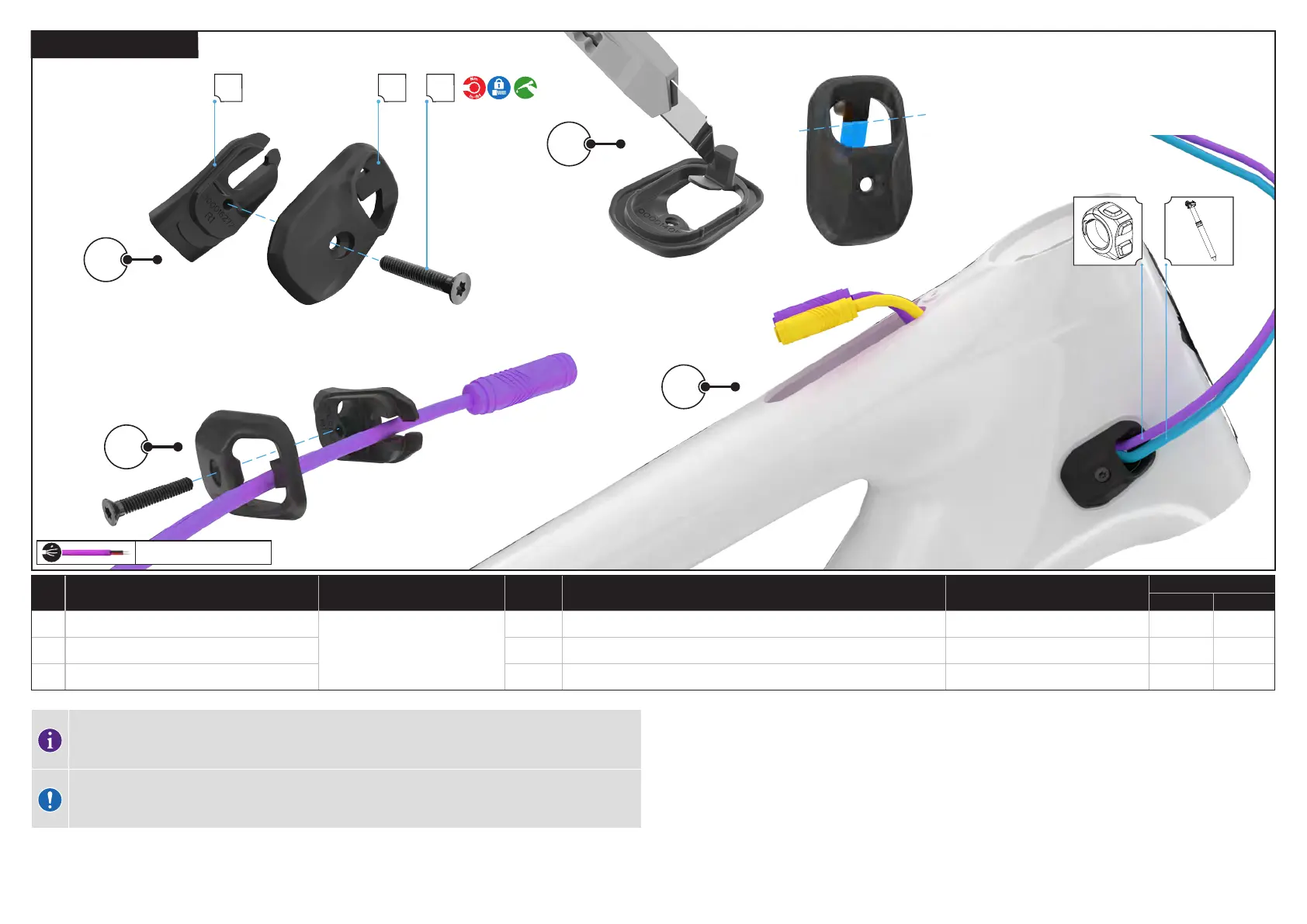
6.3.2. DRIVE SIDE ICR PORT
REMOTE - TCU
# PART NAME SERVICE PART NUMBER QTY SPEC / DESCRIPTION TOOL
TORQUE
Nm in-lbf
A ICR cover — 2 wire
S216500007
2 ICR CVR,UNIVERSAL RACETRACK,2 WIRES,2 CABLES N/A N/A N/A
B ICR base 2 ICR BASE,UNIVERSAL RACETRACK,NYLON,BLK N/A N/A N/A
C ICR guide screw 2 M3 x 18 mm x 0,5 mm p, bolt
T10 Torx 1 9
The trail remote connector cannot pass through the ICR guide base holes and must be threaded through
the slot located in the guide base. Removal of the tab on the ICR guide cover gives your access to the slot
in the ICR guide base.
CAUTION: Using a sharp blade can cause injury. Keep fingers out of the path of the blade when cutting.
Follow all safety guidelines from the blade’s manufacturer.
1. Using a T10 Torx key loosen the screw holding the inner and outer components of the drive side ICR port guide
together and separate the two components completely.
2. Use a sharp blade to remove the tab in the ICR guide cover.
3. Thread the remote cable connector through the ICR guide base and then through the slot in the guide base and
out of the TCU cutout in the top tube. Thread the derailleur cable through the lower hole on the non-drive side ICR
guide.
4. Slide the inner component of the ICR guide into the NDS head tube port, and place the outer component on the
frame. Using a torque wrench and a T10 Torx bit, and torque the ICR guide screw to specification.