12
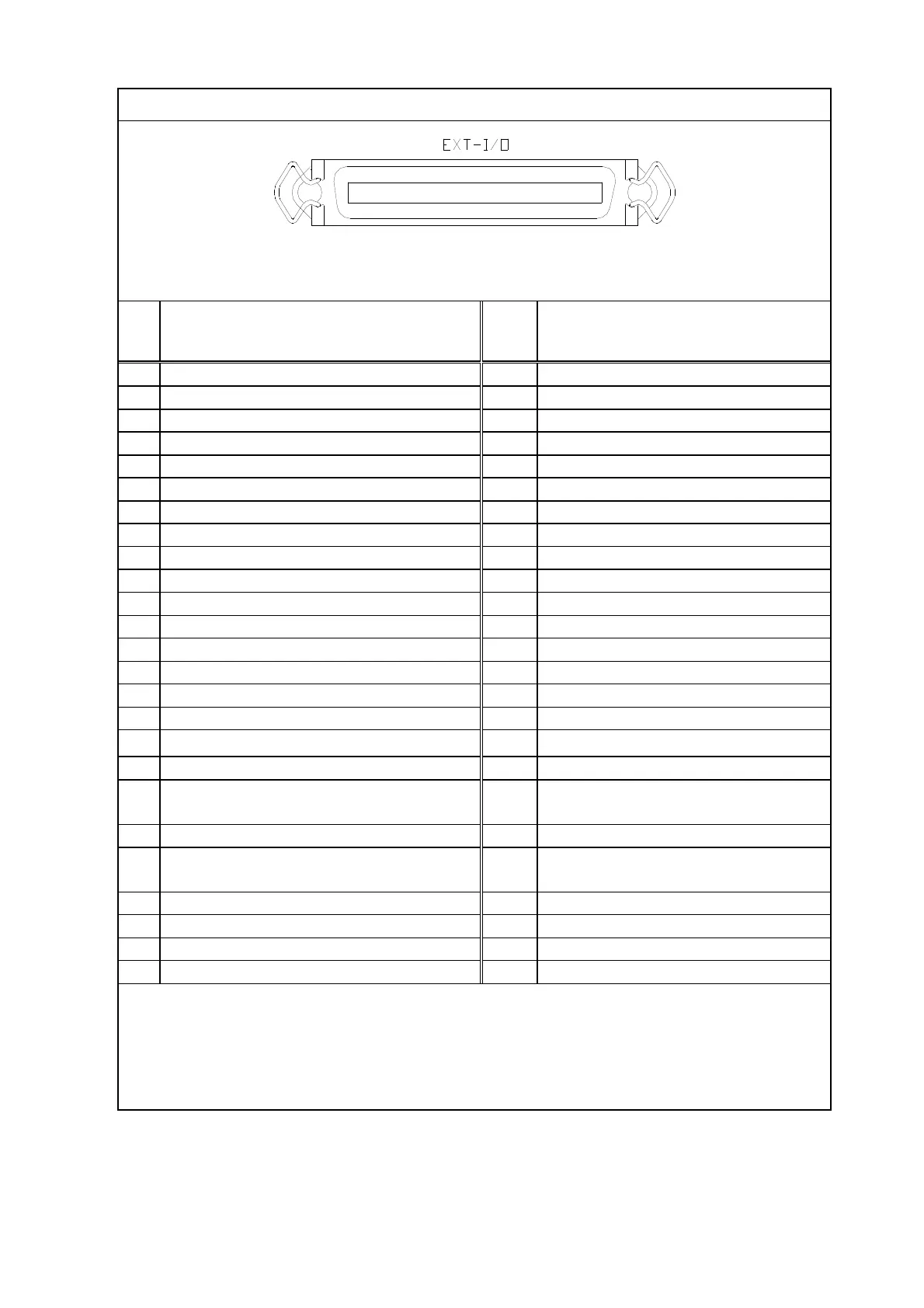
Fig. 3-5 Input/output connector pin assignment
Signal identification
nal
Signal identification
SET1 COM
SET2 COM
SET1 a
(OUT-PUT)
SET2 a
(OUT-PUT)
SET1 b
SET2 b
EXT-OUT COM
・
E
E
A
E
E A
/
(OUT-PUT)
・
A
E
E
(OUT-PUT)
A
E
E A
/
・
A
E
E
※1)
A
E
EA
/
・
A
E
E
A
E
E A
・
A
E
E
A
E
E A
/
・
A
E
E
・
A
E
E A
/
・
A
E
E
・
A
E
E A
/
・
A
E
E
・
A
E
EA/
+
(OUT-PUT)
・
A
E
E
(OUT-PUT)
・
A
E
E
・
A
E
E
・
A
E
E
・
A
E
E
A
E
E A
/
(IN-PUT)
LOCAL/
(IN-PUT)
E
E A
/
A
E
E A
/
(IN-PUT)
※2)
A
E
E A
(IN-PUT)
(IN-PUT)
A
E
E A/
1
(IN-PUT)
REC-HOLD A
E
E A / OFF
※3)
(IN-PUT)
GND
GND
GND
(REC-OUT - )
GND
REC-OUT +
• A, B, C and D in PRESSURE DATA A-b0 and later correspond to «A. B × 10 ± DC» of the
indicator. Refer to ″10. EXTERNAL INNPUT/OUTPUT″ for more information.
• Digital output common is pin 5 by standard setting.
• The digital input power is the internal power by standard setting.
• Digital input common is 23, 24, 48, and 49.
•
A
_
E
EA
of signal identification (e.g.
A
__
E
E A
) indicates the LOW status (short, negative logic).
※1) Em-Hi: 1mA(GI-M2)、5mA(GI-N8) 、 Em-Lo:10μA(GI-M2)、0.5mA(GI-N8)
※2) Use it only in GI-N8.
※3) As for REC-HOLD, GI-M2/GI-D7, X-RAY are functions in GI-N8.