15
4.3.3. Installation of WIB-N3、WIN-N2/N3 (GI-D7、GI-N8)
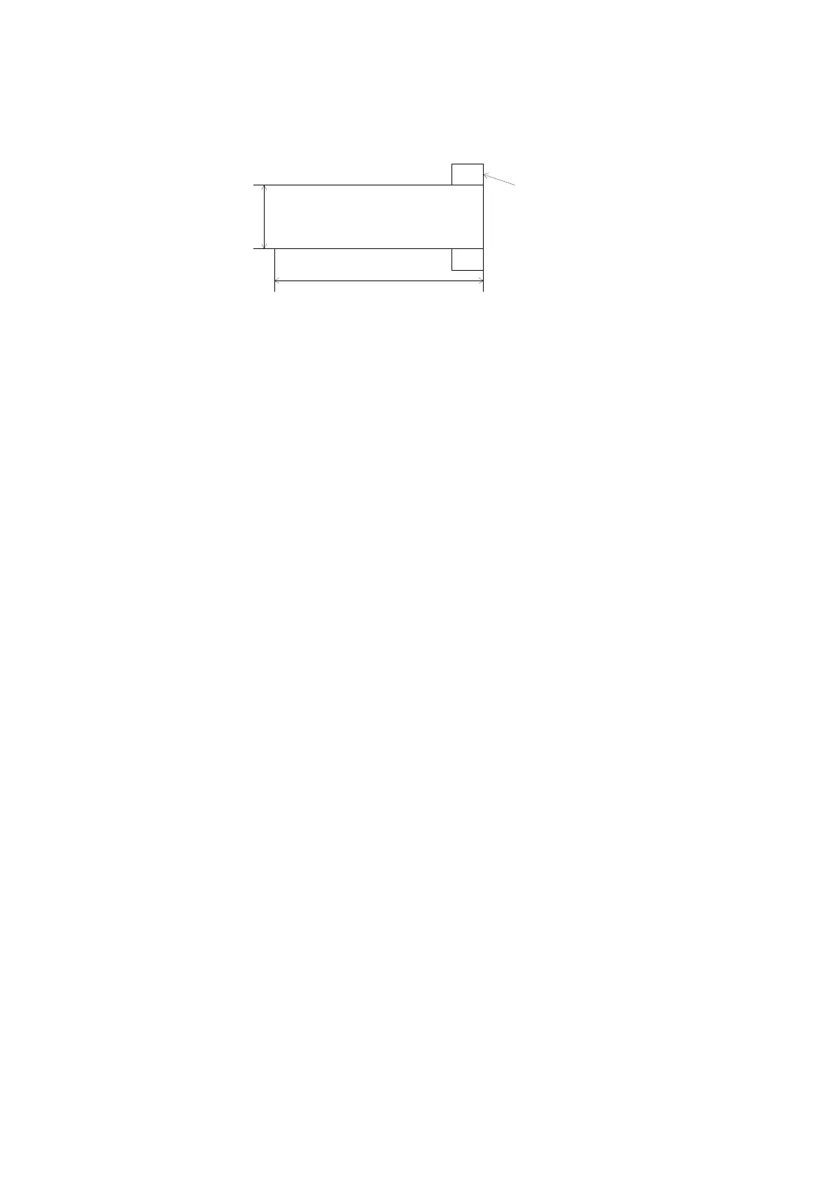
If the nude gauge is used, use a pipe 39.7 mm or more in inside diameter. Contact of the
filament with the outside wall of the pipe can be a cause of controller failure.
(Pipe used as example: OD 42.7 mm, wall thickness 1.5 mm, length 100 mm)
Fig. 4-2 Reference drawing for mounting nude gauge to short tube
4.4. Connecting the controller and sensor head
Connect the sensor head, sensor head cable and controller as shown in Fig. 4-2.
• Fix the cable so that no undue force is exerted to the connections between the sensor
head and sensor head cable and between the controller and sensor head cable.
• Lay the sensor head cable away from power lines, if possible. Otherwise, noise may
appear.
• If the sensor head cable moves, frictional electricity may be generated between the
conductor and insulator and this may be a cause of error when the measured pressure
is low.
• Avoid installation in a high temperature (above cable specification temperature) or
high humidity place. The sensor head cable temperature is 150°C as standard.
Pressure can be measured while baking with the gauge connected to the sensor head.
• Normally, the controller ground and the sensor head ground (outside wall) are
connected by means of the sensor head cable. If there is a potential difference
between the ground of the controller installation place and that of the sensor head
installation place (due to connection of the connector screw and sensor head
setscrew), measurement error may arise. In that event, install either of them
afloat using an auxiliary wire or decrease the ground resistance.
CAUTION OF USE: M-type sensor head and nude gauge
Connect the GND terminal of the controller to the ground terminal in the place where
the controller is installed. When the nude sensor is used, the vacuum piping and the
ground of the controller are at the same potential (due to contact of the connector shell
with the shell clamp and flange).
If the ground potential differs between the two, the pressure measurement may be in
error. If this is the case, mount the controller electrically afloat and ground the vacuum
chamber or mount the sensor by insulating it from the vacuum chamber and ground the
controller.
CAUTION OF INSTALLATION:
If the potential level differs between the control ground and sensor head ground (outside
wall), normal emission current will not be obtained and normal pressure measurement
may not be made.
If the sensor head is connected/disconnected when there is a potential difference, you
may get electric shock. (The connectors on both ends of the sensor head cable are at the
same potential as their ground.)
Before connecting/removing the cable, turn off the power and make sure there is no
potential difference.
Connect/remove the cable by holding the connector body. Connecting/removing the
cable by the cable can be a cause of disconnection or poor contact.
UFC-070
φ39.7
L=100
Flange
Inside
diameter