28
8.4.Selecting the Sensitivity Factor Function
→ Refer to P.35
Set a sensitivity factor. The set point as follows.
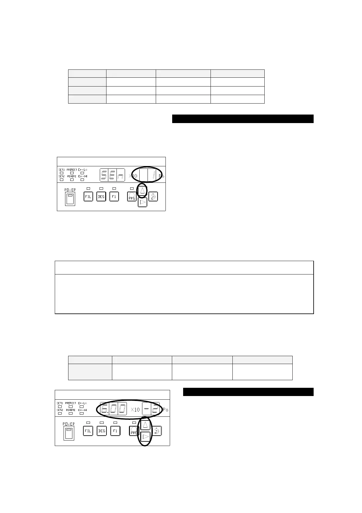
The ○ portion in the left figure blinks
after the segment indicator displays [
] for about 1 second. Each time the [∆]
key is pressed, the ○ portion in the left
figure repeats displaying [
] ⇒
[
] ⇒ [
] ⇒ [
] ...
cyclically.
To use the sensitivity factor for N2, press
the [⇒(ENTER)] key, with [
] [
] selected, to transfer control to the
SET1-
① status.
To use the sensitivity factor for OTHER,
press the [⇒(ENTER)] key, with [
]
selected, to transfer control to the SET1-②
CAUTION:
When setting a sensitivity factor, the set point action may change over depending
on the set value the moment the N2 setting is changed over to Ar setting or OTHER
setting. It is recommended to change the setting in the POW-
① status or by
stopping components from which signal is received. Check the set point set value
and sensitivity factor set value before changing the setting.
8.5.Setting the Sensitivity Factor Function
→Refer to P.35
Setting the sensitivity factor function. The set point as follows.
6.00×10
-1
~
6.00×10
-3
7.47×10
-1
~
1.66×10
-2
2.00×10
-0
~
2.00×10
-2
The ○
portion in the left figure blinks.
Each press on the [∆
numeric value of the blinking portion.
When a desired value is displayed,
press the [⇒
(ENTER)] key to transfer
①