61
10.1. Set Point Output
The internal relay is actuated (reversed) when the set value becomes lower than the set
point set value. The output is a relay contact output and one transfer (COM, a contact,
b contact) is outputted per set point.
The contact capacity is
AC:125V
MAX
,0.5A
MAX
DC: 24V
MAX
,1.0A
MAX
However, it is recommended to use it at
below 24 VDC so as not to bring the noise
source into the GI-M2 gauge (for safety of
the connector wiring).
Fig. 10-1 Set point internal circuit
AC:125V
MAX
,0.5A
MAX
DC: 24V
MAX
,1.0A
MAX
However, it is recommended to use it at
below 24 VDC so as not to bring the noise
source into the GI-M2 gauge (for safety of
the connector wiring).
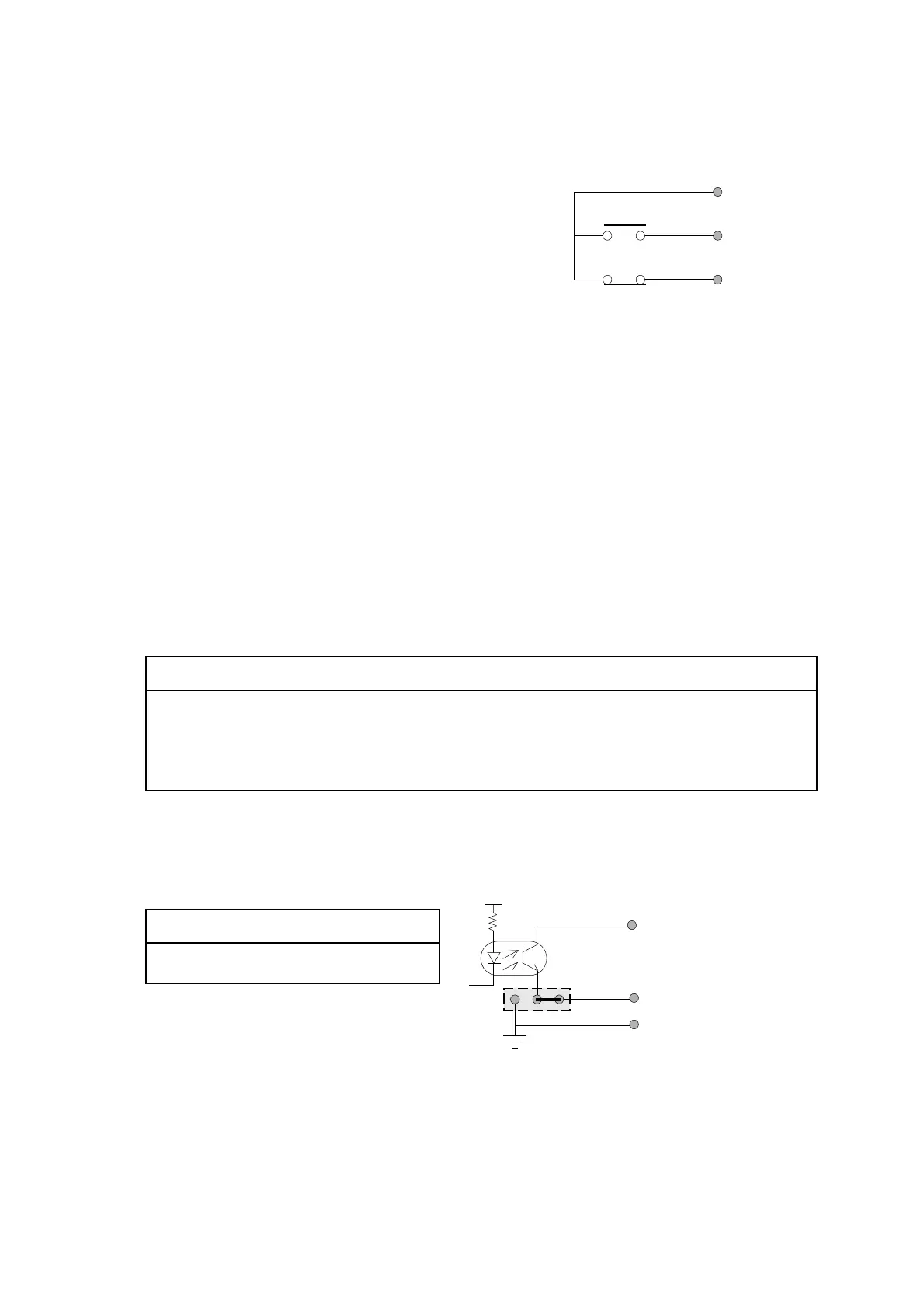
10.2. External Digital Output
The operating state, such as measured pressure value, filament ON/OFF status,
DEGAS ON/OFF status, etc. are outputted to outside as digital signals (negative logic).
The output form is the open collector output. Output rating is
[24V
MAX
,50mA
MAX
,saturation voltage 1V]
The standard setting of emitter common is pin 5 «EXT-OUT COM» of the EXT-I/O
connector.
CAUTION:
«EXT-OUT COM» is normally insulated from internal ground. To use it on
common ground, open the bottom panel of the controller and connect ″HP4″ installed
on the rear panel side to 1-2side by means of a jumper wire.
″HP4″ installed on the rear panel side to GND side by means of a jumper wire. See
Fig. 10-1 shows the digital output internal circuit.
″HP4″ on the board has been connected to the ISOside by means of a jumper wire
before shipment from the factory.
CAUTION:
ANALOG GND and DIGITAL
GND are common inside.
Fig. 10-2 Digital output internal circuit
e contact
2(27)
COM
SET1
(SET2)
1(25)
3(28)
b contact
”HP4"
External digital
output (BCD etc.)
5:EXT-OUT COM
23,48:D-GND
(24,49:A-GND)
GND
ISO